After finding out that the 2006 and up Prius includes a tire-pressure
monitoring system, I wanted to install one, or at least some equivalent
sort of warning mechanism, in my 2004.  Maintaining good tire pressure is
one of the most important factors for high MPG, as well as getting a handle
on the safety issue of having a tire go low and not realizing it until it's
too late [e.g. during a long highway trip].  TPMS makes a whole lot of sense,
which is why the NHTSA is mandating it on all model-year 2007 and up cars.
After thrashing around with various ideas and discussing possibilities in
the prius_technical_stuff yahoogroup and a bit of concept prototyping, I
arrived at a weird but workable solution.  See pts.txt for the in-depth
technical discussion and how the whole idea came into being.  Note that while
this is implemented in a Prius, it should be doable in any car with ABS speed
sensors and known locations of the signal wires.

In effect, this device displays DIFFERENCES between the rotational speeds
of any two adjacent wheels around the car, as a beat frequency from the
ABS speed-sensors mixed together.  It is shaped like a diamond because
each LED represents a side or end between two wheels.  The topmost LED
displays the spin-speed difference between the front wheels, for example,
and the remainder positionally correspond to the other pairs in an obvious
way.  An immediate objection may be that many circumstances of normal driving
will produce major deltas, such as taking a turn or even accelerating or
decelerating, but under "float" conditions on the straight and level the
green diamond should show only very slow changes in any LED's brightness.
It is then up to the human brain of the driver to interpret any anomalies.
The single low-tire warning is any two adjacent LEDs changing brightness
faster than the others, as the wheel in question turns faster.

The animation at the top is a reasonable representation of accelerating
around a gentle curve.  The top and bottom show a typical difference between
inside and outside wheels while turning, and the right and left show that
the front wheels supplying motive force really do "squirm" to go a little
faster than the rear wheels that just follow along.  Bumps generally cause
very abrupt changes, as tires receive quick variations in path length.  The
diamond really does change fairly fast under many conditions, so if you're
the type of person who is driven nuts by seeing blinkie-lights in your
peripheral vision, this device as implemented isn't for you.
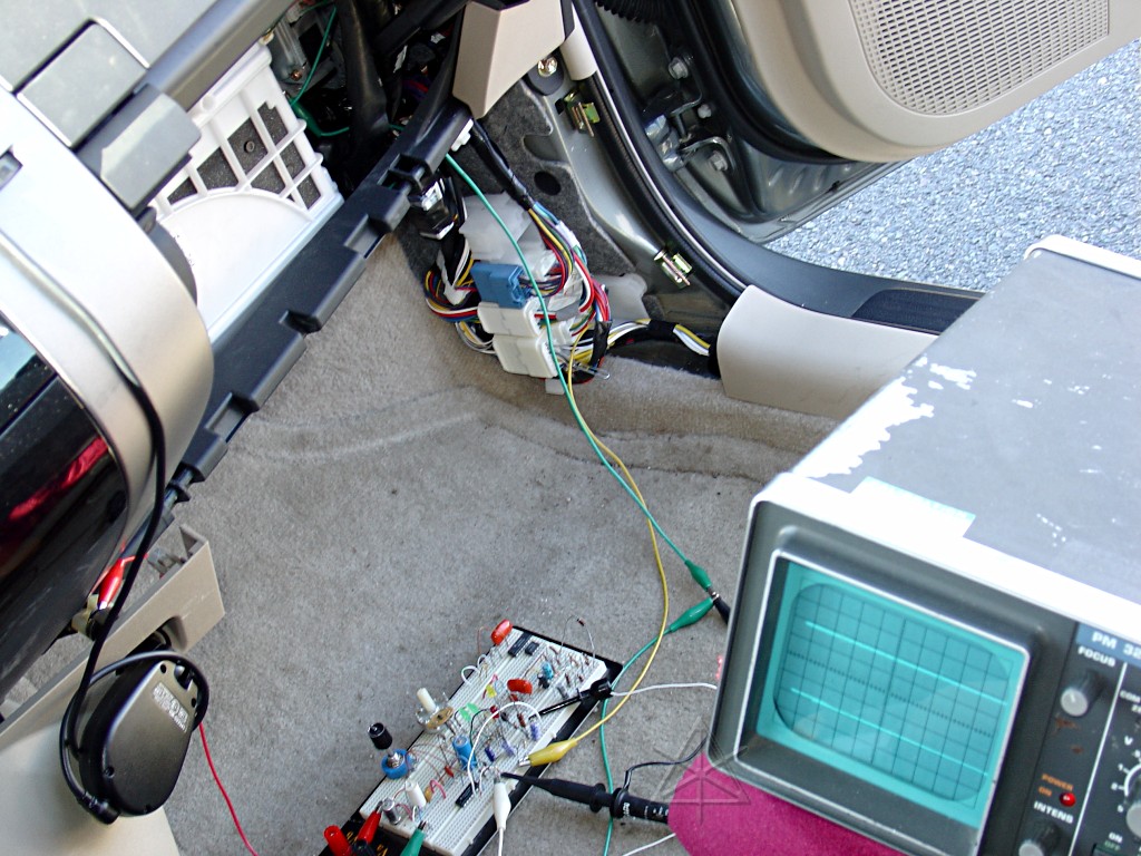
The early prototype XOR rig, paper-clipped into the rear wheel sensors
via where they pass through the body-harness connectors.  This allowed
better conceptual testing, with the downside that I had to keep glancing
down into the footwell to see what the LEDs were doing.  The preliminary
to *this* was to simply bring both signals into the scope channels to see
their general amplitude, frequency range, and other characteristics.  At
that point, switching the scope to "A + B" channel mode produced a sinewave
with varying amplitude as the two sensor signals drifted past each other and
added or canceled, and there, in a way, was my representation of what the
LEDs should do.  That first very simple test setup coupled with letting some
air out of one tire taught me that the whole thing was workable at all and
gave rise to those early reports.

The prototype had a front wheel also brought into it before this phase
of testing was done, allowing exploration of front-to-back issues too.
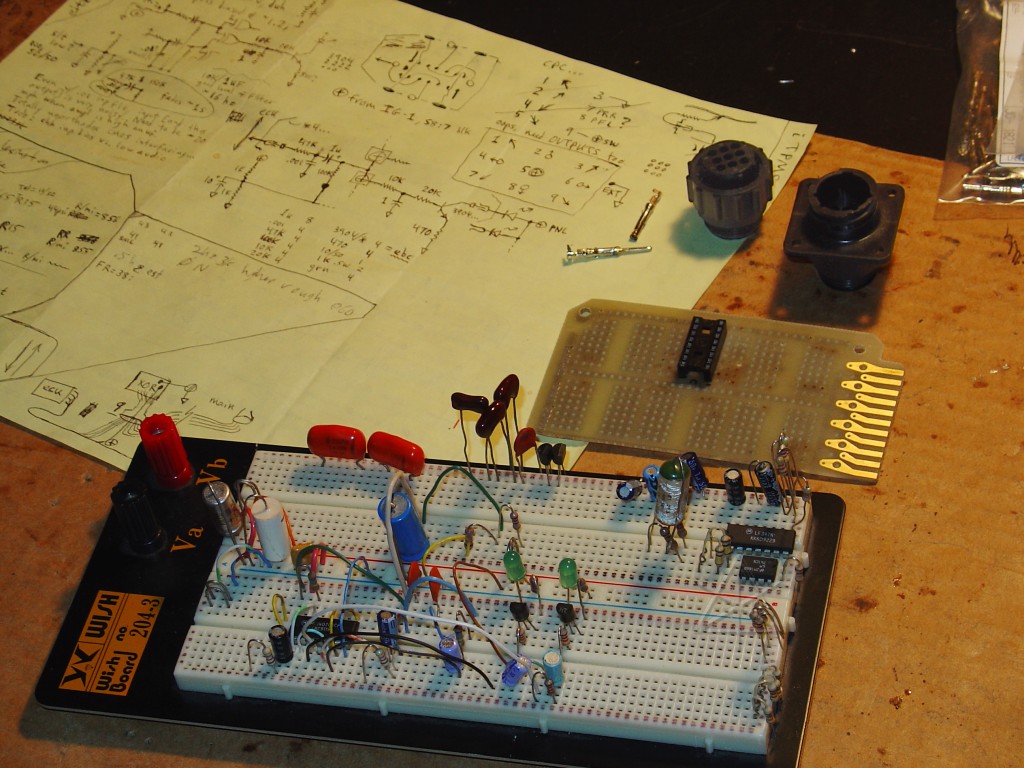
A few months and a very wet spring later, finally time to put it together
for real.  I scrounged up an old general-purpose circuit board from someone
else's long-dead project, sliced it in half, and cleaned the few irrelevant
parts off it leaving the socket for the quad XOR chip.  It should be noted
that every part of this is is put together from whatever was laying around
in the house, and no new parts were purchased.  And a lot of what's kicking
around here is way-old, which is probably why the stockroom often smells of
outgassing PVC insulation.  Fortunately, a while back I had bought a bunch of
those locking circular plastic connector [CPC] shells and a bag of pins,
which are great for projects of this sort especially if higher currents are
involved.  A close look at the yellow design-notes sheet shows the pin
assignments, which worked out in a very cute and obvious way.
The circuit begins to take shape ...
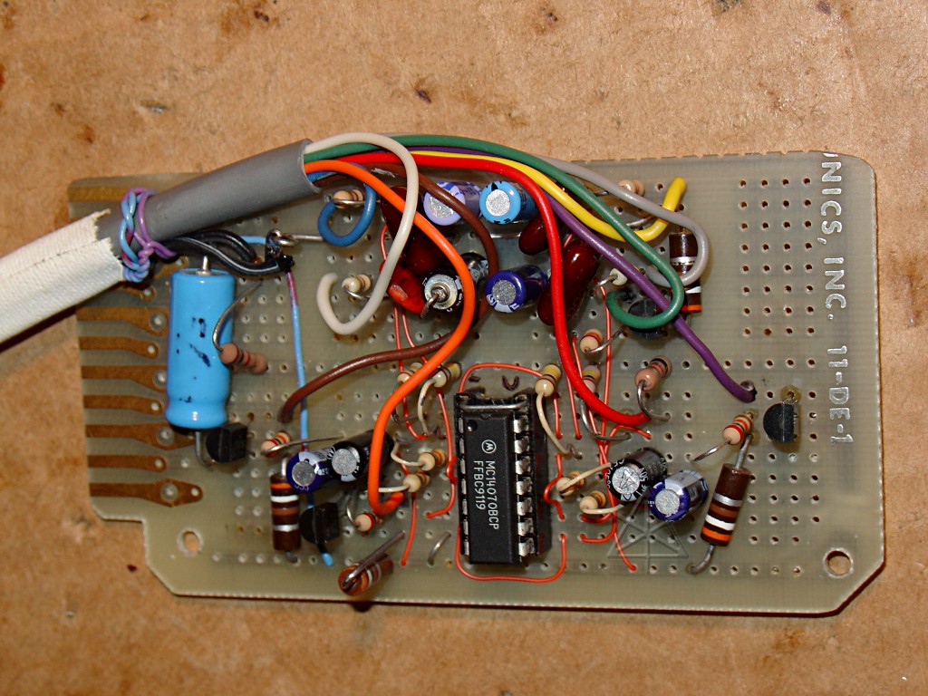
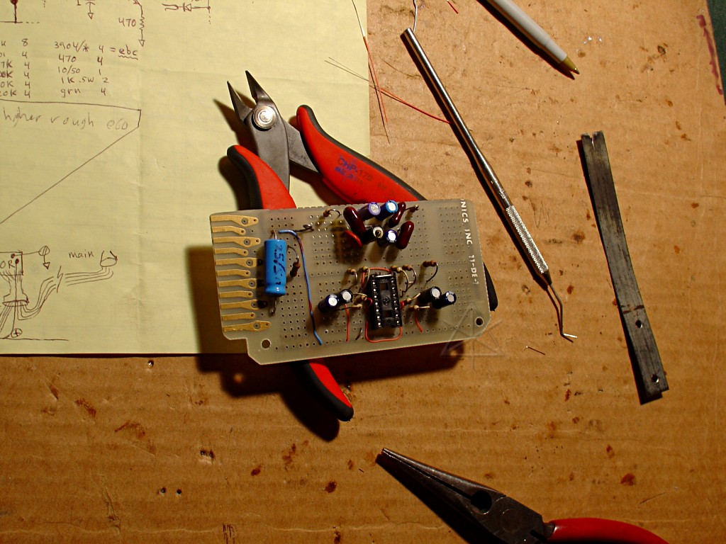
... and is finally finished after a fairly painstaking bit of hand-wiring.
   [Click the pic for excruciating detail...]
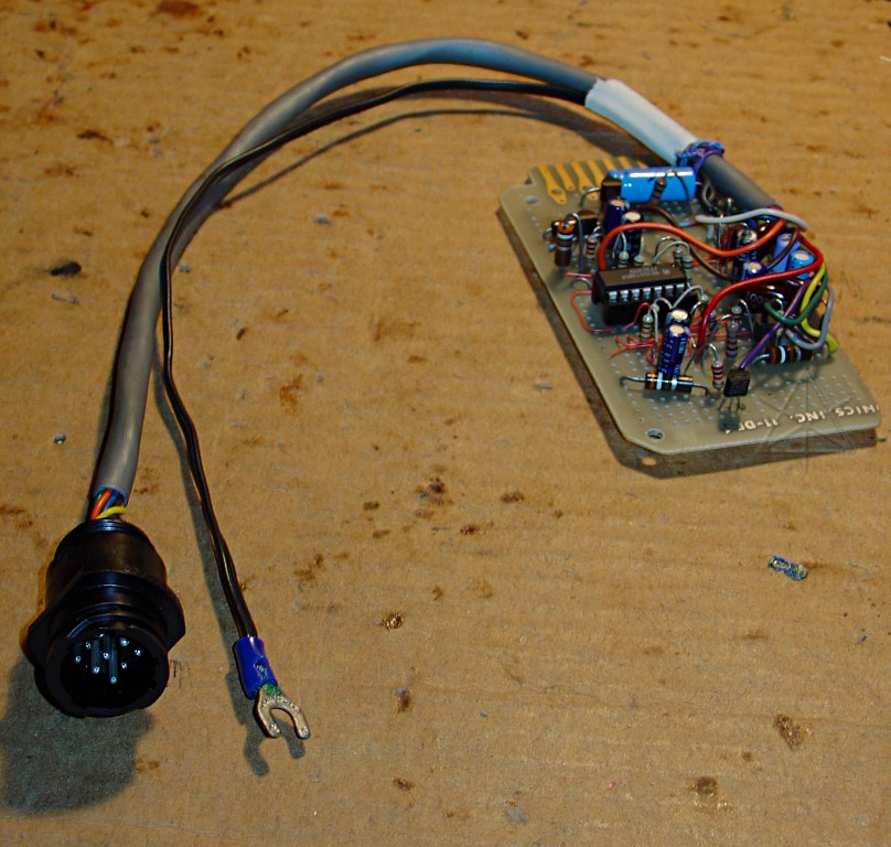
Communication to the car and the gauge panel goes through the CPC along with
power.  Since this connector only has 9 pins and I needed ten, ground is run
separately with a lug that can be stuck under any nearby fastener into bare
metal.
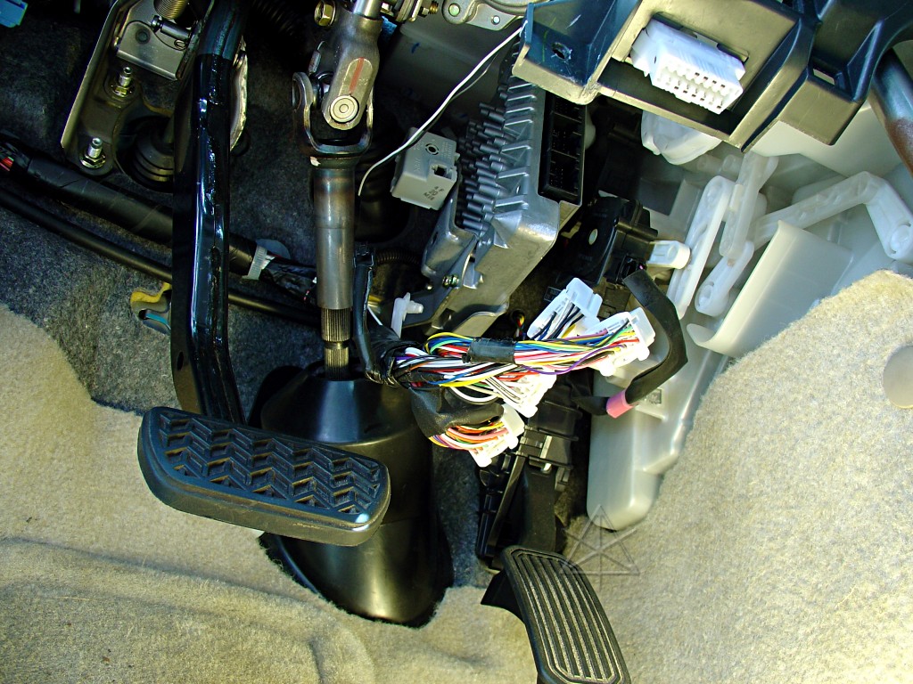
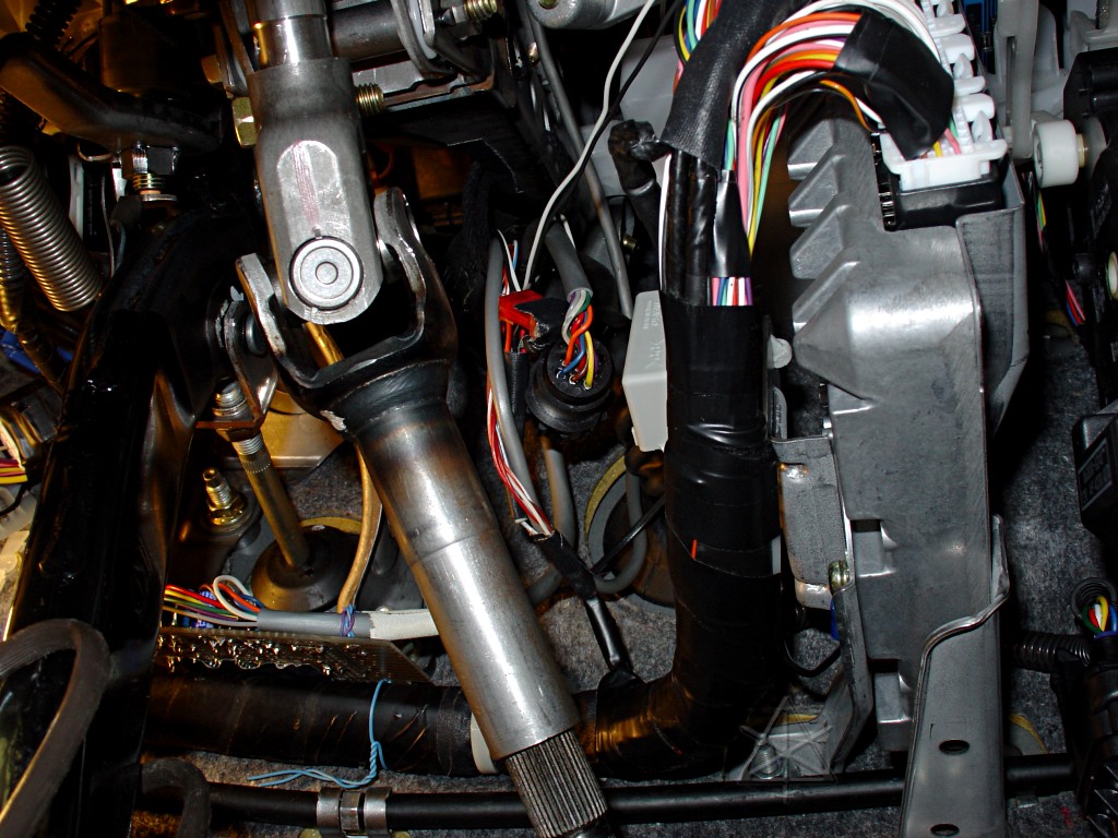
It's one thing to pull the connectors out of the brake ECU and fool with them,
but to get any real work done a few more things need to be unplugged and
disassembled ...
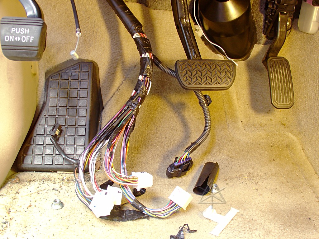
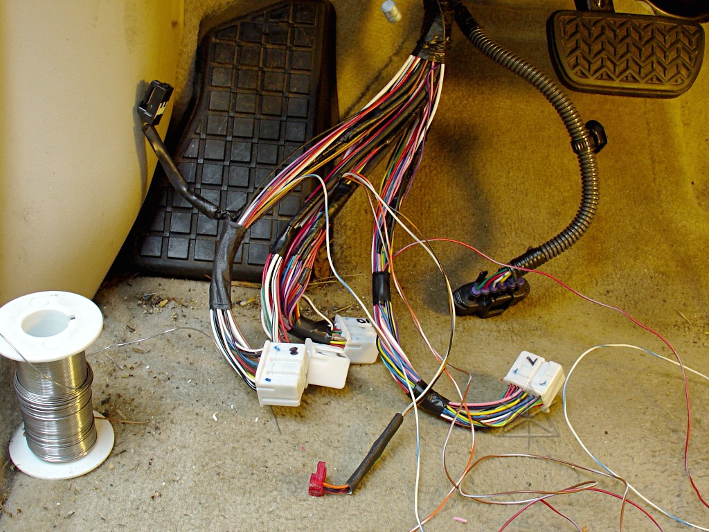
... so that the entire harness can be brought down for easier access.  The
accelerator pedal plug is part of this branch, and runs *behind* the ECU
and the tabs that connect it to the firewall.  [I cannot fathom why the
accelerator pedal has a water-resistant connector, either, right up next
to the totally non-weatherproof brake ECU plugs..]  With a bit of cramped
work, I finally got it all down and unwrapped enough to sort out the wires.

The thin taped-up bundles within the harness are some of the shielded
inputs that come into the ECU; fortunately, since I needed to tap four of
them, enough free wire is exposed past the shields that I didn't have to
unwrap any of that.
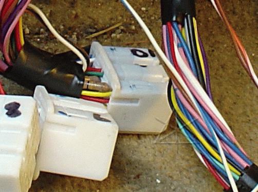
The five harness wires with taps attached.  I also decided to rework the
brake pressure monitor pickoffs a little, making them a little more
robust, running the wiring back along the harness with the new stuff, and
connectorizing them via the little red right-angle thing and a matching plug.
With a generous service loop and more tape applied to the brake-pressure
resistors, I'm less apprehensive of them breaking out of the connector.
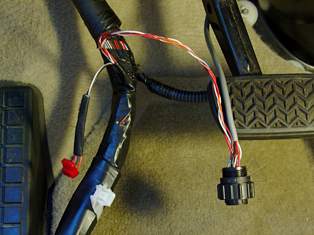
The harness reassembled and taped up, with its new branch.  The wheel-speed
taps and power are braided together just to be silly, and brought to pins
into the matching 9-pin connector.  At this point I had to think carefully
about how to route the wiring, because the grey wire coming down had to also
merge into this in a sensible way.
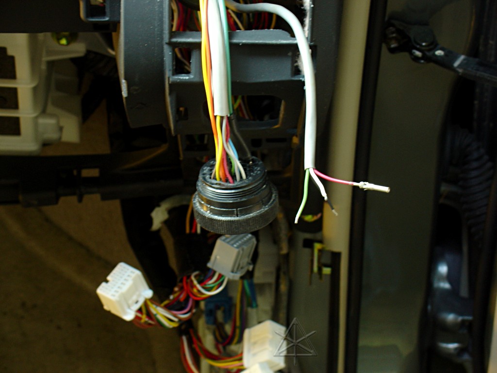
The other end of said grey wire snakes through the dash to the *big* circular
connector over on the right, that feeds the big multi-wire bus up to my gauge
cluster.  This carries the XOR board outputs to drive the four LEDs.  Here
it's just getting its pins put on, and will join the rest of the bundle once
they're inserted.

Inserting pins represented a certain level of commitment, since I don't
actually have an extractor tool for this type.  Between the ECU harness
taps and two connectors and how the wires snake onto the XOR board, I
was *hoping* I didn't screw up the positional mapping anywhere along.

It's also sort of amazing I haven't put any soldering-iron burns into the
carpeting or microfiber in the course of all this in-car wiring...
Finally the board itself is installed, and all the connectors and wiring
tucked up neatly out of the way of the brake plunger and steering linkage.
Ground comes conveniently from the brake ECU bracket -- the blue lug sleeve
can just barely be seen next to a screw, and the ground wire going to it.
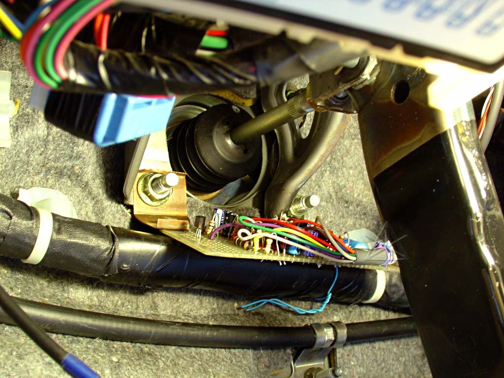
The XOR board isn't just hanging off the brake ECU harness with telco-wire,
it's got a real mounting bracket attached to a large bolt holding the brake-
pedal pivot on.  The board rests gently *on* the harness bundle, which helps
damp vibrations.  It is actually safely out of the way of the maximum swing
of the brake arm.

The reasons for mounting the board down here instead of just running the
speed-sensor signals up to the gauge panel are twofold: one, there's no good
real estate left behind the panel anymore, and two, I learned my lesson from
the brake-pressure monitors about bringing low-level signals straight up
through the panel bus.  The pressure LEDs would respond to anything slightly
noisy, notably the injector signal coming up through the same bundle, and I
fought with that for a while with diodes and suppression caps.  I only need
*one* LED to flicker when the engine is running thankyouverymuch, not three!
So the wheel-speed lead taps run a very short distance to the XOR board, and
its outputs [which are more or less current-based and less sensitive] take
the long run.  As part of the general wiring cleanup that went along with
this project phase I finally redid the spike suppression for the injector
pickoff the *right* way, over near the ECM where it belongs, and now
everything up at the panel is much quieter when the engine is running.
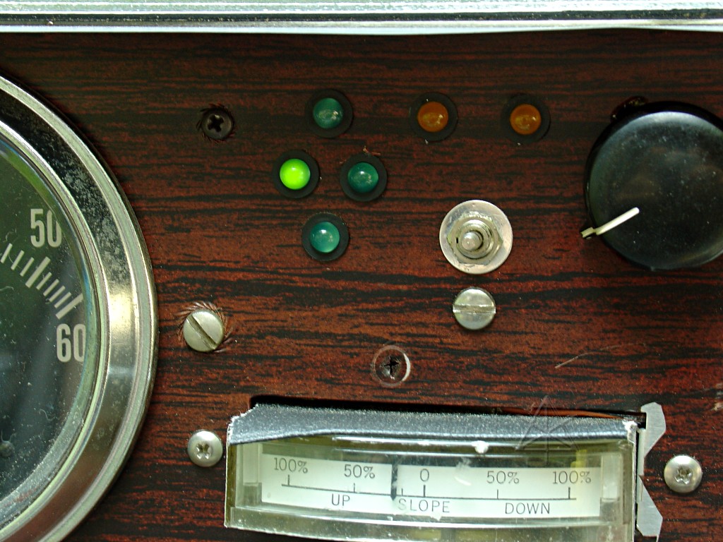
The rest was fairly easy from this point -- pull the panel, drill one more
hole and swap in the green LEDs, and wire them up.  A little testing by
spinning various jacked-up wheels confirmed that I had indeed gotten all the
positional mapping right, a major relief.  For some reason, the Left output
always comes on when the car is in Park or Neutral -- different thresholds
on the XOR inputs or something, who knows.  Once speed reaches 3 or 4 mph,
they all come on and level out and start doin' that groove thang.  See the
circuit discussion for in-depth detail and explanation of quirks.

Again, ideal behavior is very slow brightness change for straight and level
at constant speed.  However, achieving this requires tire pressures to be
adapted a little.  Everyone speaks of the 2 additional PSI needed in the
front tires to account for the weight distribution -- in fact, this widget
shows that to achieve rolling balance, that difference really wants to be 3
or 4 PSI higher in the fronts on a relatively unloaded Prius.  So a little
bit of front-to-back calibration is needed with a tire pump, but once that's
done it establishes a nice quiet baseline that can be consulted under the
same stable-rolling conditions.  Of course when the car carries a larger
load [more people, luggage, etc] that may be thrown off again, but it's easy
enough for the observer to mentally compensate.
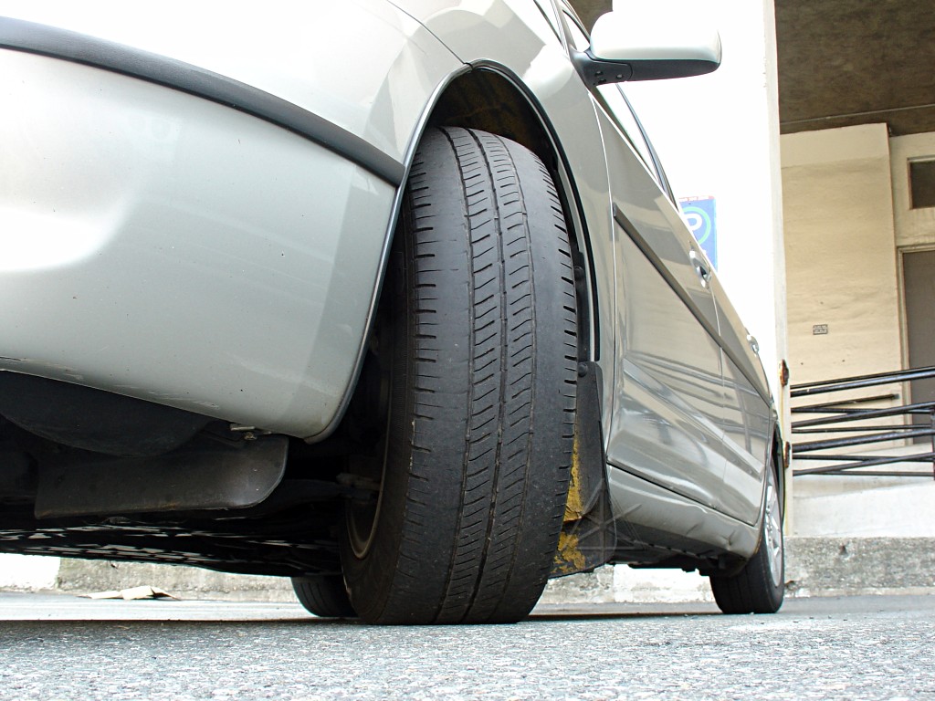
And we need to get those suckers up to SIDEWALL pressure, where they're
designed to run!  This is what happens when Integrities are run a long
distance at Toyota's "placard" pressure or what it says in the owners'
manual -- serious edge wear, because the center of the tread gets very
little load, and undoubtedly more flexing and heating in the sidewalls.
This is true for many cars and tires these days -- modern tires are simply
designed for much higher pressures than they used to be, and running them
lower than that just wastes the performance and lifetime they're capable
of.  [*Note: this is on someone else's Prius, not mine]

Going from 44 PSI down to Toyota's recommended 33 in one tire produces a
*very* visible issue with the two LEDs bordering that wheel position -- a
blink rate of as much as 2 Hz, which says to the astute observer, "FIX me
FIX me FIX me!"  And while 30-something PSI is still reasonably safe, it's not
good for fuel economy.  But seeing a persistent anomaly like that definitely
gives the viewer more motivation to fish out the tire pump and deal with it.

Parking or even driving with one side of the car in direct sunlight may
produce a fairly significant difference between the sides, and look like a
continual turn even when going straight until the tire temps equalize out
again.  If the condition persists past that, of course, stop and check for
*two* soft tires...

Obviously, swapping to the spare donut or any other oddball-sized tire causes
a major difference -- the beat frequency can become so high that the two LEDs
in question flicker very fast, and visually appear to be simply sitting at
half-brightness and not changing at all.  If that hideous yellow donut is on
one wheel of a Prius instead of a regular tire, the flicker gets very frantic
even at low speed and the eye begins to lose resolution at around 35 - 40 mph.
But even in that pathological state the remaining two LEDs should stay stable
and will continue monitoring the other three tires.  In general, not seeing
*any* change in a given LED for a long time means there's something wrong,
perhaps in the circuit or a wheel sensor, because the wheel rotations can
never remain perfectly matched on real-life roads.  [Losing a wheel sensor
would also throw an error code in the car itself.]

An obvious question is whether to take it all a step further and let a
computer do the analysis.  One should google for "tread indirect monitor"
and refer to the NHTSA and DOT commentary and rulings -- many people tried
to make wheel-speed based methodology work because of the obvious equipment
cost savings, and there are already some systems based on that research are
on the roads today.  Because of too many non-measurable factors affecting
accuracy of the indirect method, eventually they all gave up in favor of
direct monitoring via sensors mounted in the wheels and communicating via
radio link to the car.  But by leaving an informed human in the loop, who
can take all the surrounding environmental conditions into account and know
what to ignore when, this method turns out to be accurate enough for its
intended purpose, and makes a really fun little display while going down
the road.

The only real system limitation is the case when all four tires lose pressure
equally.  All warning systems aside, there's no substitute for going around
and CHECKING tire pressure regularly and inspecting their overall condition.
http://www.nhtsa.dot.gov/cars/rules/rulings/TirePresFinal/background.html
Background on NHTSA's involvement in the TPMS rulings.
http://www.unece.org/trans/doc/2003/wp29grrf/TRANS-WP29-GRRF-53-20ebis.pdf
Slides from a UN/ECE presentation on TPMS developments. Includes empirical
rolling-radius-decrease chart for different brands/models of tire.
_H* 060713