
|
| [Note: this is not a product or kit. You get to build and package it yourself, possibly improving upon the design in the process.] |
How do you know when you're recapturing kinetic energy via regenerative
braking, or just burning it off as heat in brake pads and rotors?  By
keeping an eye on the hydraulic pressure sent to the wheel cylinders
by the electronic brake actuator.  Feedback about pressure for each
individual wheel is sent from sensors in the actuator block to the braking
computer aka the skid-control ECU, so that it can make sure the hydraulic
fluid valves are having the right effect.  We tap a couple of these feedback
leads and mimic a range of pressure above zero with LED brightness.

A couple of reference documents:
BPP-system.gif -- overall hydraulic/electric system diagram
What we're after are the PFL/PFR/PRL/PRR wheel-cylinder pressure signals.
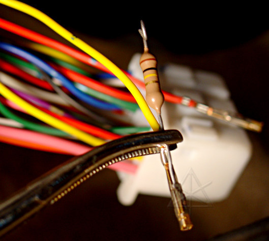
Instead of slitting and tapping the wires in this case, the pins are backed
completely out of the ECU connector, and the ends of the 100K resistors
tack-soldered into the connector lug.  The resistors hang out the back of
the plug and provide easy connection points.  Electrically, this is no
different from the slit-n-solder harness attachment method, but is removable
with very little remaining evidence if needed.  It does require a tiny tool
to push the retaining barb on the lug down far enough to release it inside
the connector.  The only real reason for doing it this way is just to try a
different method, especially since the piece of harness going to the brake
ECU is short and tightly bound and it would probably be *harder* to tap the
wiring itself without unwrapping a lot of tape.
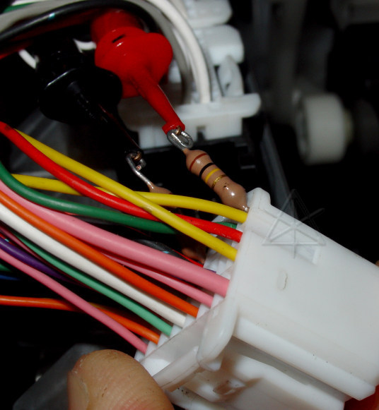
The reworked connector, with resistors, ready to plug back in.  In the
prototype, the signals feed straight up to the dash-mounted circuit
breadboard via miniclips; this eventually gets rewired for real and
merged into the ECU harness and the gauge-cluster connector.  Frankly,
the resistor leads into the plug are just a little too short here,
bringing the butt ends *right* down to the plastic, but as long as
they don't break off, maybe that helps give them better stability.
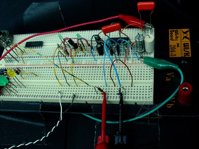
The breadboarded prototype circuit.  There are a few extra parts that
aren't doing anything kicking around, just for spares to swap into the
circuit and play with timing and thresholds and the like.  The black and
white twisted pair heads off to the two panel LEDs.
Circuit discussion
Wheel cylinder brake pressure output is described in the service manual,
in ileaf/04toyrm/04toypdf/04rmsour/2004/04priusf/05/21avn/cic12464.pdf.
The pressure sensors in the brake actuator block are powered from a 5V line
from the ECU and appear to be capable of sending output approaching 4V on
extremely high-pressure lines such as the accumulator.  Output voltage from
the wheel pressure sensors is specified over a range of .3V at zero pressure
up to about 2.5V at maximum pedal effort or 10 MPa.

Real-life observation indicates that wheel cylinder sensor voltage sits at
0.49V at zero pressure, and only reaches 1.5V or so under VERY strong foot
pressure on the brake pedal.  Voltage seems to reach 1.3 before hitting the
second stage resistance of the stroke simulator.  Therefore is practical for
the circuit to "top out" at 1.2 or 1.3 volts input because we're really only
interested in the low end of the scale, where we want to know if any pressure
is being sent to the wheels at all.  We'll certainly know by other means when
strong friction braking is being applied!  Thus, the intent of the circuit is
to mimic the most critical wheel-cylinder pressure range with LED brightness.

The pressure inputs are sensitive, high-impedance shielded lines.  R1 ensures
a high-impedance tap to the sensor line between the actuator and the ECU, and
brings the voltage [ideally, through another shielded cable but not strictly
necessary] to the detector circuit.  C1 helps filter out high-frequency noise
that may be induced from surrounding electronics.  The combination of R2, R3,
and R4 set a DC gain of ten relative to ground, amplifying the pressure-sense
voltage up to swing between 4.9 and the 12-14V positive rail where the output
is clipped.  The LM324 is chosen for its ability to track input signals down
to the negative rail, which we get fairly close to at zero pressure.

R3, R4, and C2 are configured to provide a higher AC gain, such that a change
in the signal is briefly amplified more and produces a 1/4 sec or so spike in
the direction of change which then settles back to track the new DC level.
This enables visual perception of *changes* in brake pressure as well as
constant levels, so increases -- such as when regeneration cuts out -- draw
attention with a little brighter flash of the LEDs.

R5 and D1 supply the base of emitter-follower Q1.  The emitter of Q1 simply
tracks one junction drop below the base voltage, providing enough current to
light both LEDs since the op-amp has limited source-current capability.  The
chain of D1, Q1's base-emitter junction, and the two LEDs add up to roughly
a 5V drop with a little slop on either side, thus when the op-amp output is
at 4.9V very little current is passed through Q1 -- between 1 and 2 mA, making
the LEDs just barely visible.  Increase in base voltage causes LED brightness
to track fairly linearly up to the clipping level.  LED2 is the actual
indicator, mounted on the instrument panel for easy viewing, and the string
of LEDs is sort of a quick-n-dirty zener diode equivalent to establish a
slightly fuzzy threshold.  Thus, The LEDs should all be selected to have a
2V forward drop at a nominal 10 - 20 mA current.  Q1 can be almost any
generic small NPN.

Note that one circuit is needed for each pressure sensor of interest.  The
prototype only monitors PFL and PRR since those both appear at the more
accessible lowest ECU connector.  This should give adequate representation of
control to front and rear brakes, where the major distinctions are made.
Full independent four-wheel indication is probably not needed, but if you've
got that quad op-amp in there already, go to town.

Some observations:  Light braking at speed does show a brief pulse from a
very small increase in wheel cylinder pressure, although the majority of
stopping torque comes from regeneration.  Theory is that this is a preloading
hack -- a means of making sure the pads are right at their contact point but
not to drag them excessively, so that when physical braking is needed there
is no delay in moving *to* the contact point and transitions are smoother.
In the rear brakes, it probably just overcomes the shoe return spring tension.
A braking request that exceeds the regeneration limit clearly begins bringing
in the rear brakes first, to avoid front-end dive and balance out the vehicle,
before applying pressure to the "big guns" up front if needed.  The transition
from regen to physical as the vehicle slows through 7-8 mph is obvious.  There
are several intriguing dances that happen between front and rear at times,
either due to small processing delays in the skid control ECU or active
management of vehicle dynamics or maybe some of both.

Slight variations in rotor thickness or drum diameter can be noticed while
the car is rolling and the brake pedal is held steady.  Those variations
*should* remain slight, despite the fact that the change-detection circuitry
tends to exaggerate the pressure deltas.  Since electronic braking removes
the physical feedback to the driver, there's no way to feel the onset of
problems with warped rotors and the like.  The monitors could therefore serve
as an early warning device, by showing brighter pulsation that changes with
car speed.  This may be a good argument for instrumenting all four wheels!

One really annoying circumstance is when a bump of just the right size or
time-constant is hit while regen braking -- the torque blip causes the ECU
to get confused and give up on regen for quite some time, transitioning
to physical brakes for no real good reason.  The pressure indicator makes
this obvious.  No means of recovery other than waiting long enough has
been found yet [and it's difficult to experiment if what you really need
to do is STOP].  The best bet seems to be shifting quickly into "B" and
letting the engine spin to bleed off some of the energy; regen charge
current into the battery is also generally higher in "B" and you can recover
a little more energy than by simply continuing on physical brakes alone.
_H* 050715, 050821