|
|
Valve timing and vacuum drop investigation |
For some time I've been trying to understand a certain observed nonlinearity
in manifold vacuum with respect to Prius engine RPM at highway speed.  It
seems that in a relatively narrow region centered around 2300 RPM, vacuum
drops from 4 - 5 in-Hg down to 2 or so, and otherwise remains steady at one
or the other over wide RPM ranges.  Since throttle position does not seem
to make a large corresponding jump, my interim conclusion had been that the
variable valve timing is responsible -- lower vacuum caused by a slight
retardation of the intake and thus more of the cylinder charge pushed back
out into the plenum.  Someone from Prius_Technical_Stuff added the theory
that at higher RPM the inertia of air moving through the intake runners would
have more of a scavenging effect per intake stroke, thus the valves could be
closed later but still provide the same effective compression.

But I wasn't completely confident about the cause without getting some hard
data.  Efforts to read VVTi parameters with a scantool had failed, always
returning 0 or some other meaningless, invariant figure.  It isn't clear if
that's the fault of the ECM misreporting it, or the tool's inability to parse
the data correctly.  No test or measurement procedures are given in the
service manuals, other than simply making sure the sensor waveforms look good.

So once again it's time to get down to the real source, and scope the cam and
crank sensors that the ECM uses to determine the timing for everything.  Both
are similar magnetic reluctor devices, issuing a pulse when a piece of ferrous
metal passes close by, usually in the form of a tooth on a serrated wheel.
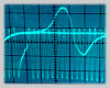
This is a generic [albeit somewhat inaccurate in real life] representation of
the cam and crank pulses as we would see them on a scope -- they possess the
characteristic shape of rising as the tooth approaches, dropping sharply
negative as the tooth passes center, and then returning more slowly back to
zero as it leaves.  If another tooth immediately follows, the waveform's
positive and negative slopes look about the same, but it's clear that the
negative slope is the actual finest-resolution trigger point and any positive
or zero slope is a "valley" transition from one tooth to the next no matter
how long it takes.  This is a bit clearer in the actual scope traces below.

The 1NZ-FXE mill in the Prius uses a "36 minus 2" crank wheel, i.e. 34 teeth
with a gap where two more teeth are missing.  This conveniently maps to 10
degrees per tooth slot.  The ECM syncs up with the base timing rate of passing
teeth and then looks for the missing pulses as an absolute reference as to
where the crank is.  The cam "wheel" only has three teeth on it [at 90 degrees,
thus a "4 minus 1" configuration] and works similarly.  Here are some pictures
of the real things, courtesy of Galaxee from Priuschat and her husband who
spends his days armpits-deep in this stuff and brings home all the coolest
discoveries.

The ECM uses the relative timing of both as feedback to determine how to
control the variable valve-timing actuator, among other things.  [Of course
everything else derives timing from these signals too, such as when to fire
injectors and plugs, and the high number of teeth provides enough resolution
to allow misfire detection from small speed variations.]
Exactly when these gaps pass the sensors is apparently not strictly based
on #1 top dead center as might be easily assumed; for example, #1 TDC in the
Prius engine appears to be when the gap is oriented straight forward at 90
degrees but where the sensor [green arrow] sees it, TDC occurs at the 23rd
post-gap crank tooth just as the output signal starts swinging negative.
The assumption is made that the positions of these sensor triggers is always
the same relative to the crank and cam themselves, so no cumbersome "re-learn"
games are necessary as with some other cars.

In this case, we don't really need to know the absolute relationship because
we're just looking for *relative* intake timing changes while running.  There
are several basic ranges of valve timing, as shown on this chart from Toyota:
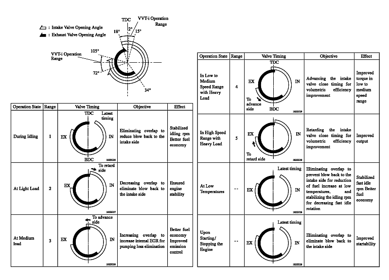
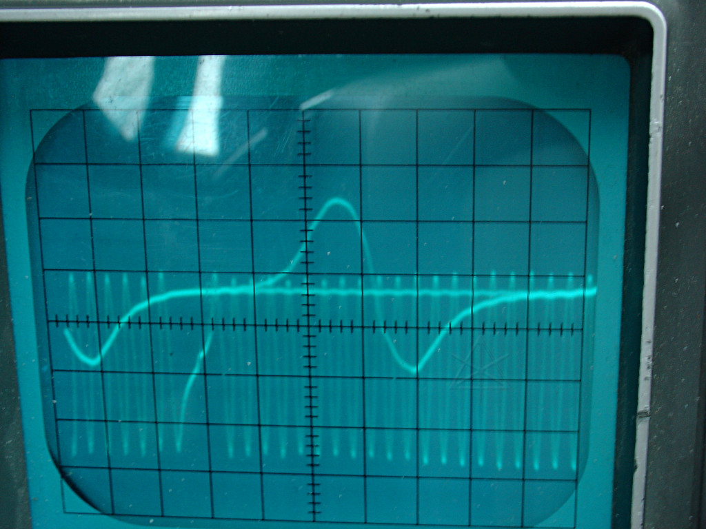
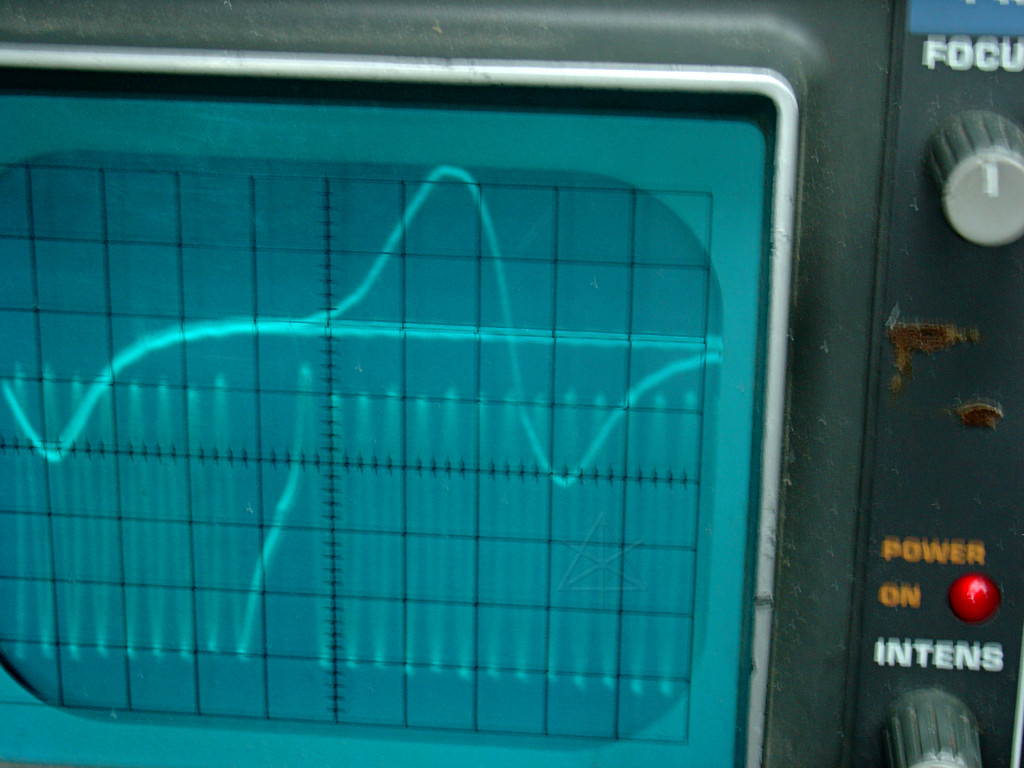
What I'm really looking for is whether my observed vacuum drop corresponds
to a transition from range 4 to range 5.  Given the way the Prius does
throttle management, the engine can be considered under "heavy load" almost
any time it is producing meaningful power -- this is one of the things that
give rise to its high efficiency.  From there, it's all about RPM to effect
any change in requested power output, and the remaining question then becomes
what is considered "low" or "high" RPM.

Another early approach was watching the oil-control solenoid output, which
isn't useful either -- other than full retardation at idle and warp stealth
that sends the duty cycle to a minimum, it always runs about 40% -- timing
changes are done by a very temporary duty cycle shift to nudge the oil valve
one way or the other, and that's just too transient to see on a scope.

So what's left is to try and scope the relationship between the cam and the
crank directly, using the cam signal as a trigger.  Even with triggering,
getting a stable picture is rather fiddly because the overall frequency keeps
changing with engine RPM.  But eventually the trace could be stretched just
right such that the negative-going slope from the first cam pulse would
always line up at the left.  Two or more trace times usually overlay the
shutter time, often doubling [and blurring, argh] the images.  Each of the
traces below is a link to a larger picture, in case a closer examination
is desired.
|
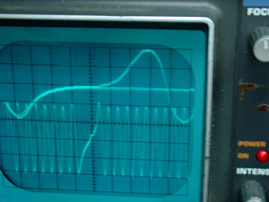
| Base idle |
|
|
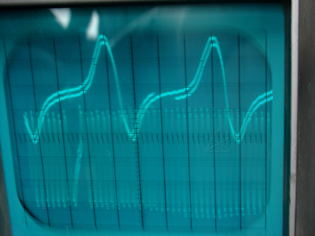
2000 RPM
Vac at 4 - 5 |
2400 RPM
Vac at 2 |
|
Cam seems to correspond with 7.5 crank intervals; an advance of 20 degrees
from idle. The pictures aren't really clear enough to determine any difference across the vacuum drop, however. But nothing says I need to stay on the same timebase as at idle, so I clicked it up a notch and managed to capture an expanded pair. The cam gap and second tooth are overlaid in two trace cycles. |
|
|
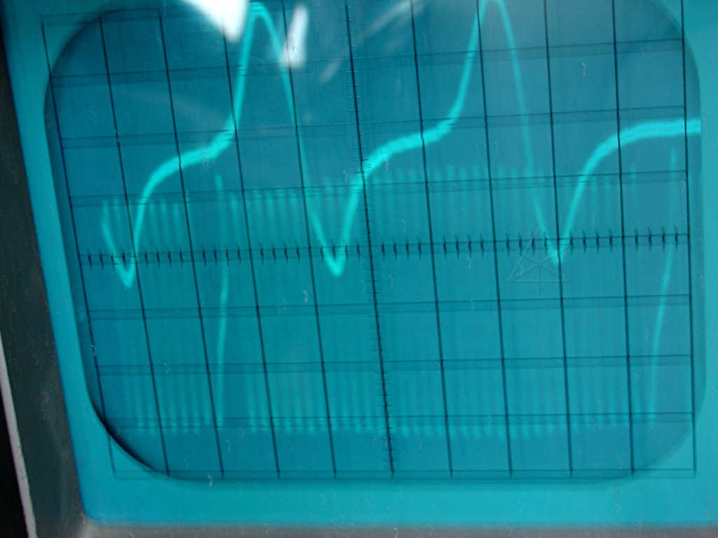
| 2000 RPM | 2400 RPM |
|
Now the relationship is clearer, and we can observe that it is also
unchanged between the two speeds. Compare these to the idle baseline, too. | |
So, that whole theory about valve timing retard affecting vacuum, at least
at these RPM ranges, is busted!  Now what?  Well, the only other possibility
is the throttle after all, so I set the laptop to recording RPM and the
throttle position over a whole range of driving conditions, and just
made a scatter graph out of it.  [Select for full-size]
We can easily see the granularity with which throttle position is reported,
among other things.  A higher vacuum scenario would trend points toward the
right and down, while lower would move to the upper left.  Now that we've got
the viewpoint of long-term trends, there appears to be a small but definite
upward tick in throttle opening around 2300-2400 RPM, so that seems more likely
as the cause for what I see on the vacuum gauge.  But I'm still at a bit of a
loss as to why it's not more linear in the first place.  It may still have
something to do with MG1 transitioning from negative to positive rotation,
but I still think that's coincidental.  In any case, on the interstates it's
the difference between 35 and 25 MPG instantaneous, and it is becoming
generally agreed that perceptible MPG gains can be realized by trying to
stay in that higher-vacuum region as terrain permits -- not exceeding 2200
or 2300 RPM unless really needed.

The sweet-spot article has been slightly updated to reflect
this, removing any outright statements about valve retard.

_H* 070506