 |
 |
| Series | Parallel |
Series/Parallel hybrid topology
More direct (and efficient) path to wheels
Electric-only drive capability -- "full hybrid"
Downsized components -- engine & motors can help push
MG1 and MG2 interchangeably power each other
"Closes the loop" for power transfer
Linked via the Power Split Device
PSD is a single planetary gearset -- nothing new here
Model T Ford
Almost any modern A/T is full of them
Essentially, it's a differential -- just lopsided!
Another view of the same thing
"Generator" and "Motor" really are misnomers
Both can perform either function
"Motor/generator" is the accurate term
Yes, the axles have their own differential too
(Just not shown in many of these diagrams)
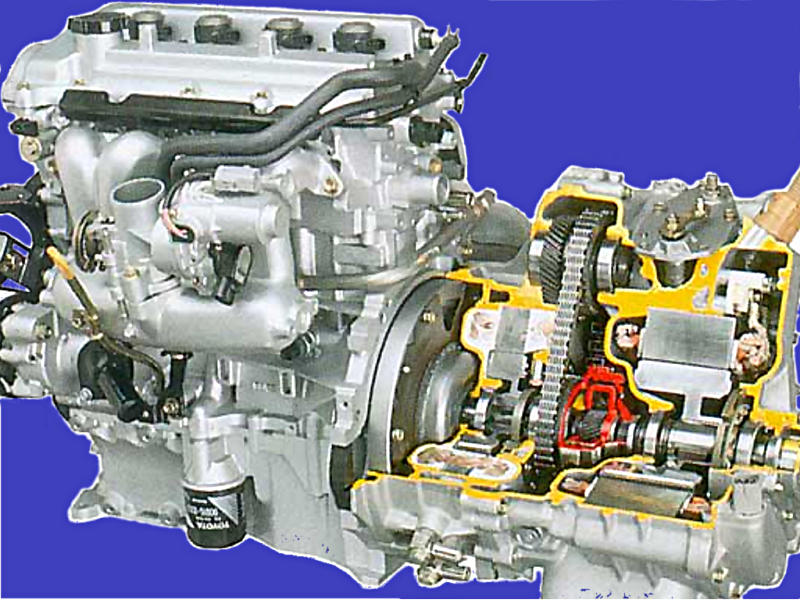
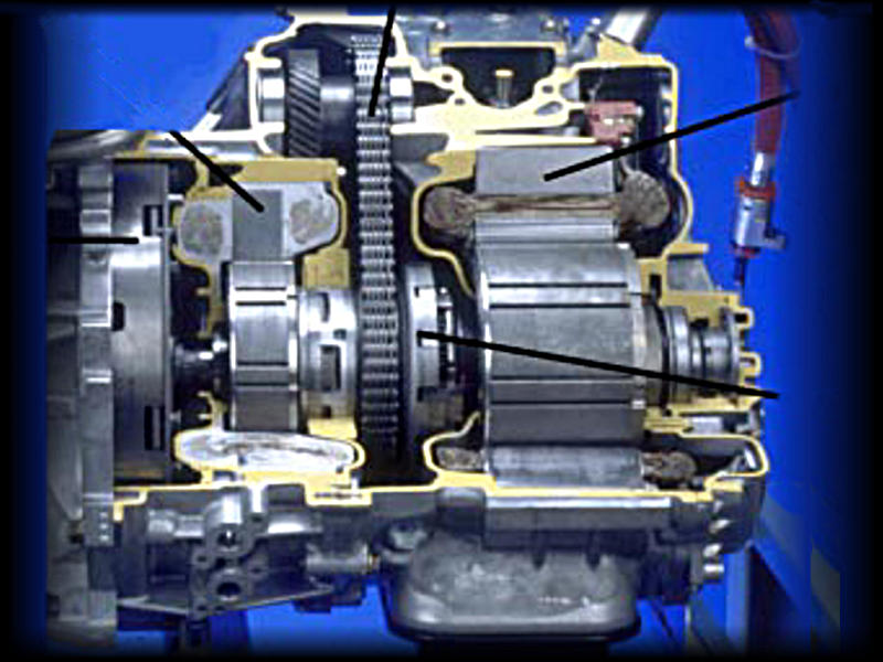
Toyota's trade-show transaxle cutaway
Two electric motor/generators
MG1 == "generator", charging, starter, and torque-balance
MG2 == "motor", traction and regen
Mnemonic: 2 is larger than 1
(And they're both smaller than the engine!)

Engine shaft through center
Connects to planet carrier (inner black line)
Runs a small fluid pump at far end
MGs run on sleeves around that
MG1 is sun gear
MG2 is ring and road (outer black lines)
...that's a little hard to see here -- there are
THREE concentric parts where the chain takes off
Engine torque splits 72% to wheels, 28% to MG1
NO mechanical shifting, except park
"Continuously variable" is done electrically
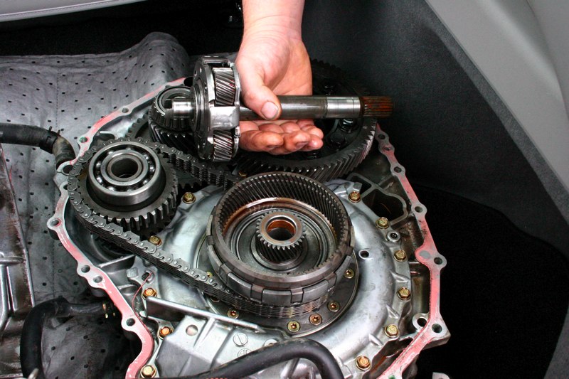
This tech stole the show!
Lacey, WA alternative fuel fair
A whole Classic transaxle to play with
He's holding the engine shaft / carrier
Final drive from ring multiplies torque
Chain take-off reduces side loading
The Prius has a "4.11 rear"
Engine shaft, sun gear, ring turn independently
Rotors are strongly magnetic!
Keep laptops, cards, etc away
This unit is *heavy*
As you might imagine, with all that iron inside
Toyota considers this a FRU
Simple and (hopefully) reliable
And yet there are complete overhaul instructions
Independents can maybe rebuild them?
Opportunities will be rare
MG2 slings a little oil
Maybe makes up for pump not turning?
Gen 2 rotors are smoother
Here's the 72/28% split again
Simplest graph of torque/RPM relationship
Read RPM (for all) down left side
Read road speed (for MG2 only) down right
MG2 RPM has direct correspondence with MPH
Useful engine (ICE) RPM 1000-5000, or OFF
Gears treated as levers/pivots
Hold back MG1, and the car moves
Just like sand under the spinning tire...
Two shopping carts and a broomstick?
It's all about balancing loads
Play with the models
Understand torque-transfer
Meet "Torquey the Muppet"
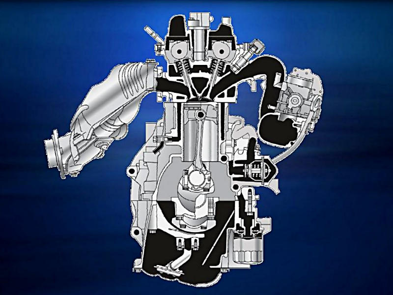
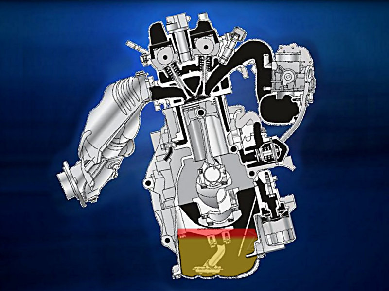
Rework of 1.5L Echo plant
This is good for 50+ MPG by itself
Closely matches ASE composite type 3
Many efficiency hacks...
Offset crank
Narrow bearing surfaces
Low-tension rings
5w30 or lower oil
Belt only drives primary water pump
Low friction in general (can turn with one hand!)
VVTi with Atkinson/Miller intake
Lower compression, higher expansion
Nominal 13:1 turns into 8:1 on intake
Extracts more net energy from gases
Significantly better FE, slightly less torque
Original Atkinson linkage changed piston stroke
see excellent animation at
http://keveney.com/Atkinson.html
Miller simplified w/ delayed intake close
Pushes a little mixture back into plenum
Compression tests *will* be lower...
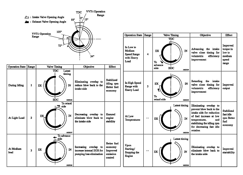
Several operation modes/ranges
Variable intake, fixed exhaust
Range 4 yields high MPG!
Full retard during fuel-cut "warp stealth"
Internal EGR via valve overlap
No external plumbing to fool with
This is becoming typical in VVT systems
How to monitor valve timing?? Scantool lies
Chain cam drive
Direct bucket lifters
Adjustment rarely needed if ever
34 tooth CKP (2 missing)
3 tooth CMP (1 missing)
No scantool "CMP learn" needed
VVTi actuator driven by oil pressure
Control solenoid nudges spool valve back and forth
Vanes inside sprocket hub set relative cam angle
cam/crank timing discussion:
http://techno-fandom.org/~hobbit/cars/vvt/
ETCS (not just in Prius now)
1st gen repair: fix/adjust
manual describes TPS R&R
2nd gen repair: throw it away?!
Manual doesn't even get into it...
But it's the same $750 of serviceable parts!
TPS angle must be restored
There's apparently no auto-learn
But no IAC to fool with, either
Diagnostic: listen/feel the motor PWM
It actively fights you when it's working
Failsafe rest position via return springs
Two springs set a default 15% TPS, slightly open
Dual-wiper pot for redundancy-checking
VTA1 used as main input
Two PCV hoses
One above plate, one below
Coolant loop around throat
Clean/lube butterfly is useful service item
Can clean/service without disconnecting coolant lines
MAF only, no MAP or BARO
Air box has charcoal HC filter
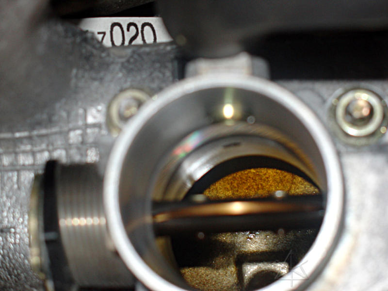
Oil sump in intake is very common
Several theories on why -- PCV, blowback, ...
May also include fuel distillates
Oil overfill seems to exacerbate it
P3191 "engine does not start"? Look here
Especially in cold weather
Oil viscosity may be a factor
Throttle-butterfly edge crud could cause sticking
More 1st-gens having problems now
http://techno-fandom.org/~hobbit/cars/tb/
3.7 quarts does not mean 4 quarts
1/4 inch BELOW full mark is about right
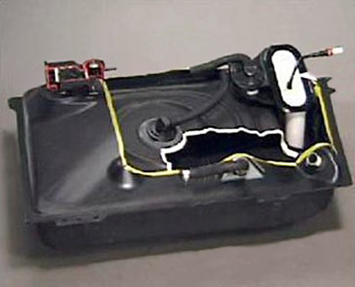
Bladder inside metal gas tank
(US/CAN market only)
Reduces vapor volume and loss
Stiffer and hard to fill in cold weather
Gauge sender is off to side, parallel plumbing
Returnless fuel system
Single-speed pump & regulator (in tank)
Nominal pressure 48 psi
No rail pressure feedback (would have been nice)
EVAP tests include bladder leak detection
Tank air pulled to intake and tested by A/F sensor
More pix and teardown/discussion:
http://priuschat.com/forums/tech/30593-bladder.html
Next
Fuel system
Diagnostics
14 ohm saturation injectors
Easy injector-wire access at ECM
Fuel supply tube & fittings under cowl
Scantool pump activation
No FP fuse, and "C/OPN" relay is semi-buried
Best pump-power access is under driver's kick-panel
Test adapters are hard to find
Toyota says "purchase new fuel tube"
<Insert whiney "fuel systems WTF" rant here...>
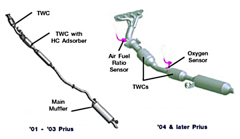
1st gen: O2 sensors
And HCAC adsorber (see next slide)
2nd gen: Wideband A/F at B1S1
Differential output -- both sides 3.something volts
Current-based, can't really scope it
Some scantools confused about its "voltage"
Post-cat is normal O2
Sits low, somewhat vulnerable...
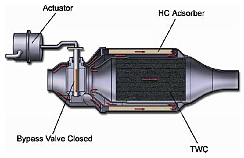
1st-gen special second cat
Vacuum-actuated valve
Closed for warmup
Open for HC purge later
Problem: it rusts and sticks
Esp. in the Salt Belt...
P1430, P1431
Can possibly lube and work it loose
But it requires frequent attention
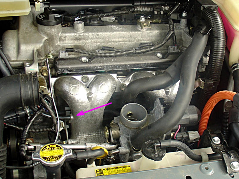
Vacuum fitting still present in '04+
Not used in 2nd-gen but still on the manifold
Convenient vacuum-gauge takeoff!
Some throttle-body hoses visible here
Note front PCV wear pattern from air box

Heat storage and retrieval system
(US/CAN only, not JP/EU)
Hot coolant "put away" in insulated tank
Used to preheat head/cylinders at next startup
Three-way valve directs coolant flow
Preheat is reverse of normal flow into head
Warms right around combustion area, lowers emissions
Normal radiator and cabin heater
With the addition of an electric circulation pump
(Remember that "furnace" thing?)
Scantool-driven bleeding procedure
Hex bleed tap semi-hidden under LHS radiator brace

Vacuum dewar bottle
Holds about 3 liters
Frequent collision victim
Has one of three engine coolant drains
Fairly easy access past fender liner
But don't mangle it (or its clips)
Bug: wasted preheat
Pump-in happens on most power-ups
But what if you're not going anywhere?
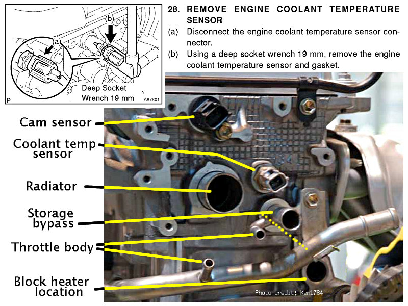
Which sensor is which here?
The manual may mislead
Oil pressure: switch only
Pressure transducer would be a nice hack...
Coil-on-plug ignitors
Iridium plugs, 100K
Pull and anti-seize them well before then!
Hole for electric block heater
(see "heatgames" webpage for many details)
http://techno-fandom.org/~hobbit/cars/heatgames/
The inverter blocks easy access to here
The ... what? Is that a car part?
Look around the engine
Examine throttle area
Find sensors (or difficulty of access)
Find my block heater
(do NOT remove it -- thermal grease)
Find the fuel pump power
Under the LHS kick panel is easiest

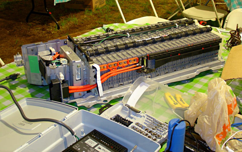
This is what everyone asks about
Answer: "lasts the life of the car"
Charge management is the key
40% - 80% limits, seeks 60%
NiMH best present chemistry right now
High charge/discharge currents
But lithium is rapidly gaining ground
Note service-plug wiring!
Also contains battery ECU, relays, prechage resistor...
Hall-effect current-sensor donut is what I tapped
Tour de Sol hack-job charging experiment
... not particularly safe, but proof of concept
We don't need Toyota's magic charger
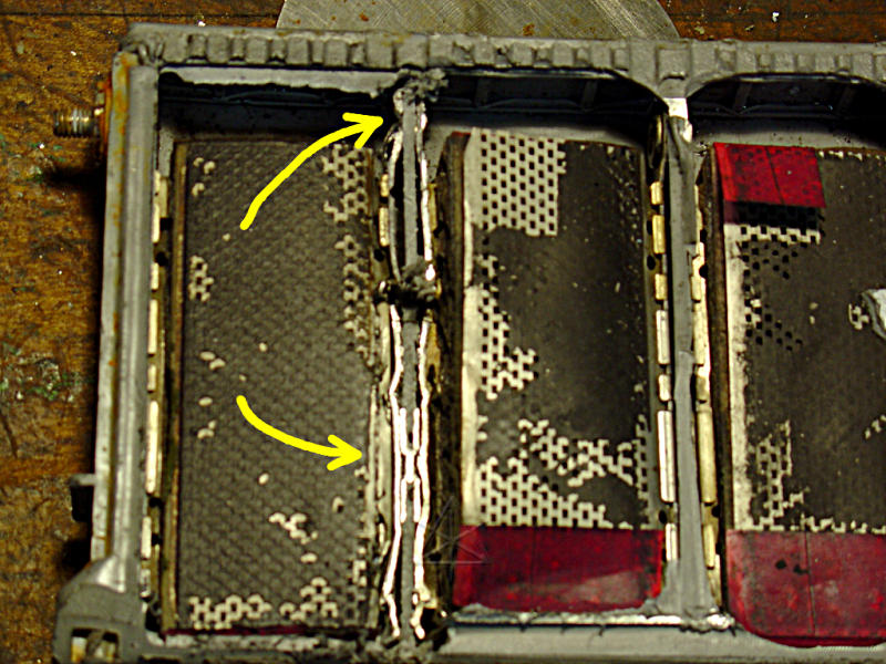
Prismatic modules
6 cells at 1.2V each = 7.2V
6 or 6.5 Amp-hours
Thermistor cavity
Classic pack: 6 Ah
38 modules == 273V
50A max charge/discharge
2nd-gen pack: 6.5 Ah
28 modules == 201V
100A max charge/discharge
Secondary cell interconnect for more current
Better cooling surfaces
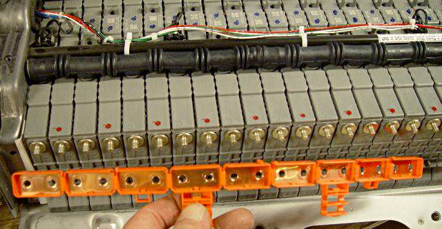
Modules are all series-connected
String voltage monitored every 2 modules
ONE weak cell can ruin your day
Can read block voltages on scantool [~16V]
Real-life operational voltage is higher
273 --> 300, 201 --> 220
Compression rods hold the pack together
Otherwise, cells can easily bulge out
Warmed/cooled from cabin air
Batteries are happy at human "comfort zone" temps
Not sized for distance -- ~600Wh avail
Used for energy bouncepad, not the day's commute
1.5 or 2 miles max on "full" charge
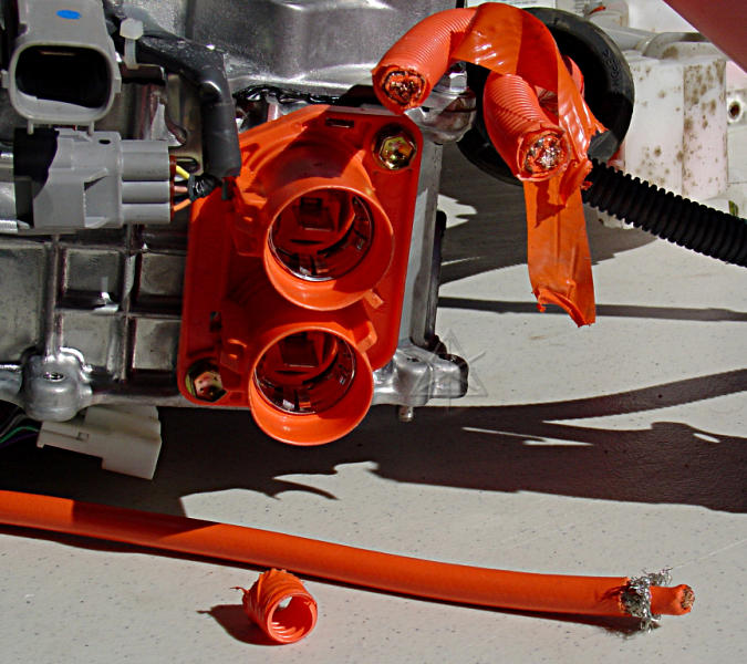
Entire HV system is isolated
Battery, relays, wires, inverter, motors
Any chassis leak detected as a ground-fault
P3009 and system shutdown
Coaxial cable and shielded connectors
Penetration/damage likely to cause ground-fault
WARNING: Battery ECU sense leads still hot??
That ECU plug is orange for a reason
Components can be megger tested
But read the manual on how:
500V max, and all low-voltage electronics disconnected
Can track down ground-faults piece by piece
Do we know what we're looking at here?
Study the basics on motors and inverters
1st-gen electrical system
One of about 300 patents covering the car
Basic MG1, MG2, inverter shown here
Many lessons from industrial motor-control
Toyota had to design their own semis --
off-the-shelf wasn't good enough!
Analog position resolvers for commutation
Tamagawa-Seiki "singlsyn" type, quadrature output
Feedback loop includes the computer
Bridge PWM control sent straight from ECU
2nd-gen system has several improvements
Buck/boost converter, steps up to 500V
Push motors faster, regulate charging
Higher efficiency motors
Updated IGBT power modules
Same position resolvers
Electric A/C with its own inverter
Variable speed, saves energy...
Run from HV battery, lots of power
Single bleed resistor drains all caps
And it's a funky one; see next slide
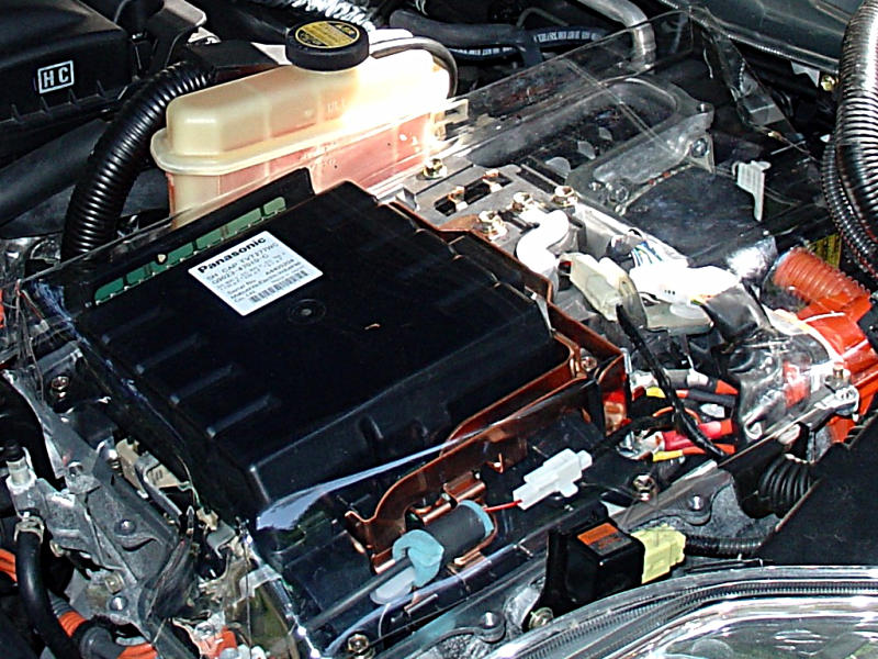
My clear cover for the "naked" exhibit
Not a whole lot to see up top
Major interconnects (200V, 500V, motors)
Capacitor module (separate cans in 1st-gen)
Green card is 64K bleed resistor assy
See "ginv" teardown webpage for in-depth detail
http://techno-fandom.org/~hobbit/cars/ginv/
Water-cooled, separate radiator section
Middle layer is a cold-plate
Pink tank is coolant reserve
Inverter can be shifted aside w/o draining
Some items accessible underneath
AirLift works well to refill if drained
Listen to the pump, look it up ...
Coolant drain in-line w/ transaxle hoses
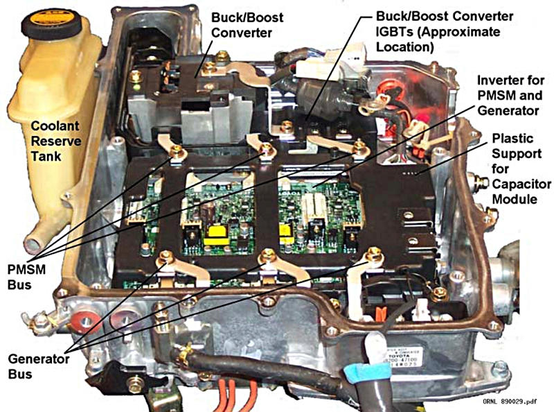
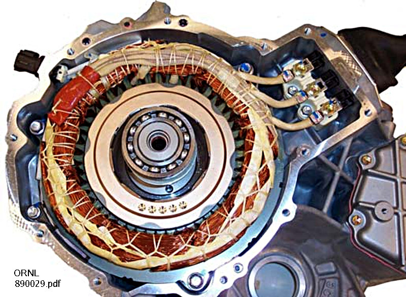
Oak Ridge 890029.pdf shots
Capacitor module removed
PWM chop frequencies 5K and 10K
You can hear this while driving
Funky modulation schemes, based on speed
ECU sends 3 control leads + "gate"
Turned into six for 3-phase bridge
Gate disables control, such as for Neutral
Interlocks on covers/lid
And on 2nd-gen service plug, too
Easy enough to bypass...
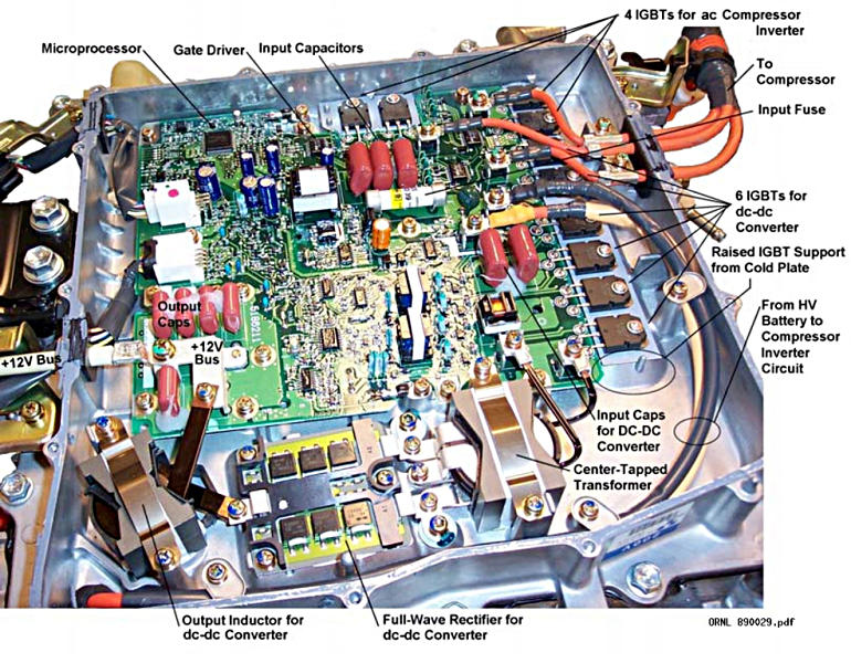
DC/DC converter and A/C control
If both fail, might be that 30A fuse
Your tax dollars at work
Argonne/Oakridge papers are all public
MG1: ~12-15 kW, MG2: 50 kW
1st-gen slightly less
295 ft-lb @ 0-1200 RPM
~ 150 lbf tangential per pole at air gap -- times eight!
and that's *before* final reduction
Three-phase permanent-magnet synchronous AC
Eight poles, four electrical revs per rev
1st-gen motors are parallel-wound
2nd-gen motors are series-wound
Higher voltage, but less current
Motor windings can be a boost converter
Argonne/Oakridge *missed* that very important fact
We can demo this easily -- crank-n-spark
Waveform very similar to injector pulse
I have a webpage up about it...
http://techno-fandom.org/~hobbit/cars/boost-hack/
"Exploded" sub-pack
Pull spare inverter apart, ID parts
Electrical experiments
Play with 3-phase
Be the inverter -- can you keep up?