|
My "flagship" APC SU2200 uninterruptible power supply, featured in
prior articles,
had developed a weird problem.
Normally stored unplugged on a table in the basement between serving events, it
quietly sat there for years when it wasn't on the road for brief periods.
Once in a while I would plug it in to top up the eight AGM "brick" batteries
inside [which is mostly what makes it so *heavy*].
I didn't think too much about it in between.
Then one evening, it randomly started beeping. Not the typical beep-beep-beep-beep pattern that all of these UPSes make when running on battery, just one long one every so often. I went downstairs to investigate, and found that the "brain" was powered up and it seemed to be trying to start itself without any action from me. The behavior was similar to what happens when the "on" pushbutton is pressed, but the timing was all weird. This was mighty odd, but given its location in the basement, I figured maybe humidity had gotten into some bit of the circuitry around the pushbuttons ... took the cover and front panel off, and cleaned up the switch board and the area around both ends of that sketchy hardwired-in ribbon cable that connects it to the main board. That seemed to fix it, so I closed it back up and got on with life. About a month later, it started acting up again. I fooled with it a little more, including trying to plug it in, and it kept randomly switching to running on battery anyway. The battery bank itself was fine, even if about eight years in service at that point -- the voltages were spec, and there was no visible degradation in the bricks [the usual symptom that they're toast is that they swell up, often solidly wedging themselves tight into the tray]. Since I'd already cleaned up the suspect circuit areas, now I was at wits' end as to what was going on. I declared the thing haunted, disconnected the Anderson connector from the battery which finally shut it up, and figured I'd debug it some other time. That time came a few months later. I unwired the battery and slid all the bricks out, and they all looked perfect and had well north of 12V on each one. With the unit thus made lighter, I took it upstairs and put it "on the slab" for testing. I hooked up four of the bricks and a series resistor to give it a nominal 48V supply but not able to start the inverter, since the problem was only that as soon as the battery was connected, the startup "beep-CLUNK" of the brains booting up happened without pushing any buttons. Evidently the start-button was false triggering somehow. Referring to my schematic, the button grounds a lead that eventually ends at some sort of custom control chip waaaay at the rear end of the main board. A full two feet away from the button, through ribbon cable and mainboard lands with stops at a couple of blocking diodes. I was really hoping I didn't have to pull the whole main board out, as it would be a giant pain in the ass. I unhooked the battery and discharged the caps and went at a few ohm tests first, to see if the start lead was being pulled to ground somewhere else. It wasn't. Everything ohmed out perfectly, and the start button brougnt the relevant lead solidly to ground when pushed. So then it was time for some active testing. Now, the start switch is a little special, as it's used as a magic bootstrap to get the main board processor powered up before it becomes an actual "on" switch. Normally when these UPSes are fully shut down -- by holding the "off" button until all the relays in the unit click off -- they draw almost no battery current at all. When they're either plugged in or the "on" switch is pushed the first time, the brain boots up but the unit's output doesn't turn on until commanded. Thus, at first, full battery voltage is present on one side of the "on" switch when it's fully shut down, although through a high resistance. So I should have seen that battery voltage or a little less on the relevant lead everywhere it appeared -- at the switch, across the ribbon cable, at the control chip, and a few other places. Instead, I saw about a volt and a half, but it seemed to vary a little when I moved the control-panel board around. By flexing the board a little, I could get it to rise to about four volts, with some jitter, but of course with the battery connected the unit was trying to power itself up and thrashing around with relays and beeping and presenting general chaos while I was trying to carefully examine things. I had to begin isolating parts of the start circuit, and the obvious place to go after first was the ribbon cable. |

|
|
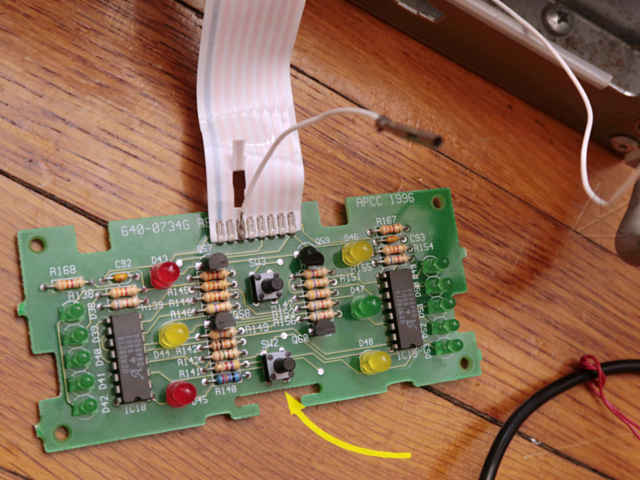
Start lead cut open in the ribbon cable
(arrow indicates the "on" button) |
|
It's profoundly annoying that this ribbon cable is never *connectorized*,
in any of this vintage of APC units.
So any investigation or disassembly always has the control-panel board
flapping around at the end of the thing hanging out the front of the unit,
and trying to desolder it would be difficult with eight plated thru-holes
to deal with and high likelihood of damaging the board.
My prime suspect was actually the ribbon cable, as it's assembled with little
lugs *clamped on* at each end in some kind of warped insulation-displacement
setup that just seems really fragile.
I figured I could break the start lead and then if it turned out the cable
was at fault, just patch around it with a separate piece of wire.
Breaking the ribbon connection did make the unit stop thrashing, but then
tacking wires onto the end lugs and bridging the start line past the cable
brought the chaos on again.
So at least I now knew the false-ground problem wasn't in the main board,
which was a relief, and I could pretty much eliminate the cable as the
source too.
The false ground wasn't a hard path, it obviously had some degree of resistance since it let a little voltage remain on the start lead. The 50V boot supply is fed through a 100K resistor, so it wouldn't take much leakage current to bring that voltage down. That could be typical of a corrosion situation, but now the question was WHERE?? The control board itself looked perfect, so maybe it was in the switch. I had tried to squirt some DeOxit in around the button piece, but there's very little space to actually get that down into the mechanism. While I wasn't happy about desoldering the switch, I fetched out the wick and worked it out of there. And of course it ohmed out perfectly again -- fully open when not pushed, and clicking solidly closed when pushed. But when connected across my re-routed start lead and ground, the voltage droop and false-start chaos once again ensued. WTF. If there was a stray path through this thing, I should at least see some non-infinite resistance with the ohmmeter?? Nope. But maybe fifty volts across it was different than the one or so from the meter -- corrosion can act like that sometimes too; let's remember that the "MO" in MOV, a device which starts conducting above a rated voltage, means "metal oxide". Also, the heat of desoldering the switch could have changed everything. Regardless, time to go see if I had a suitable replacement button in stock, or be prepared to kludge a workaround, and take the thing apart. |

|
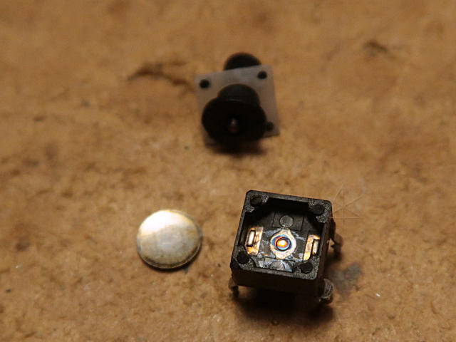
| The pushbutton split apart |
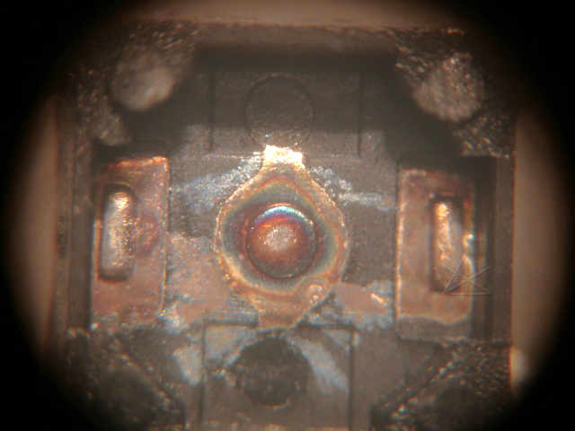
| The click-dome bridges across the two outer leads that are connected to each other internally, and then the center point goes to the other side of the switch. And there did seem to be a bit of cruft in the bottom of the thing. I threw it under the 30x scope for a closer look. |

|
| Corrosion paths |
|
Here was my poltergeist, apparently.
With 50 volts sitting across this switch most of the time and in the presence
of a little humidity, some electrolysis had evidently happened.
Now, could I re-create the leakage path as proof, even though desoldering
heat might have changed something and the click-dome wasn't present?
I hooked it up to the bench supply for a bit of experimentation.
The main supply goes up to 30 volts, but that couldn't seem to push
any current across the switch carcass.
Bigger hammer time: my big o' Frankenstein bench power box also has an output
marked with a skull and crossbones, which produces a variable DC output up to
500 volts.
In other words, the equivalent of a hipot tester, but in this case I just
wanted a quick test, so I didn't add any series resistance to limit
current.
And when I plugged the leads from the switch into that special supply ...
*SNAP!* A visible spark briefly lit in the switch carcass, and then nothing. So yeah, the corrosion did conduct at a (much) higher voltage, at least for a little while in my "overly aggressive hipot test". So what changed? Back under the scope for another look. |

|
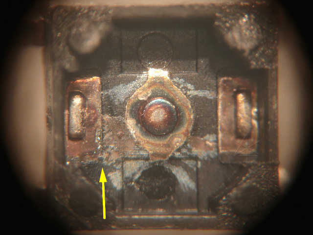
| Switch body after 500V zap test |
|
The corrosion near the arrow had pretty clearly cracked farther away from
the metal lug, breaking the conduction path, and I could see a couple of
tiny metal blobs that weren't there before.
Exorcism successful! Begone, Oxide Demon. My replacement button needed minor mods to the panel hardware, but went in with reasonable elegance and sits nicely flush with the panel faceplate. |