[Most pictures are linked to larger ones -- use for more detail]
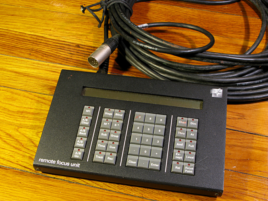
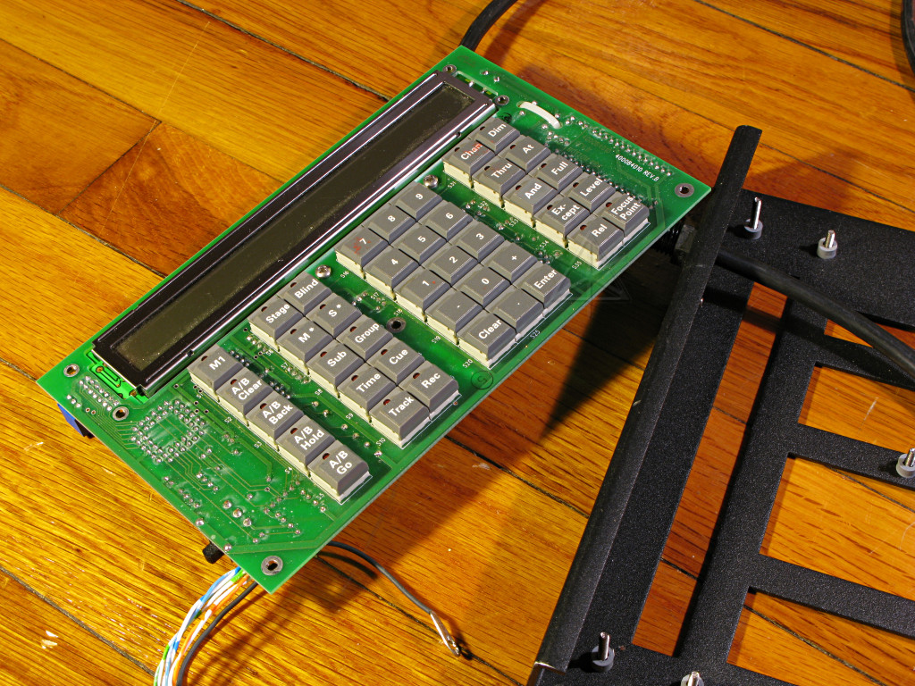
The larger ETC lighting consoles come with an optional kepyad and display
unit called a remote focus unit (RFU, usually pronounced "are-foo") that
plugs into one of several locations throughout the venue to do some basic
board control.  In any given installation, XLR-6 jacks might be located near
the stage, up in some catwalks, etc -- wherever one may have a need to bring
channels up and down for focusing but it would be inconvenient to reach the
main board.  The RFU can be held with one hand and comes with a longish cable
hardwired into it.
The RFU used at Milton Academy's Kellner Performing Arts Center (KPAC) had
been flakey for a while, and apparently ceased working entirely a few days
before I was there for a hang.  So I offered to just bring the thing home and
try to work it over and make sure all the wiring was solid.

Now, I had had this unit open briefly one time previous, to at least take a
look at the wiring, at which point the tether cable was moved to a slightly
different position relative to the entry gland on the back of the unit and
that seemed to temporarily fix its problem of randomly powering on and off.
But I guess that didn't last long, or the problem had returned in a slightly
different form -- now it powered up okay, but the RFU couldn't transmit any
data even when plugged straight into the back of the console.  I knew that it
could *receive*, because its display changed when I typed keys on the main
board.  But it was clear that the wire near where it goes into the RFU case
was not in very good shape overall, and I figured to just whack a couple of
feet off of it and rewire the end.
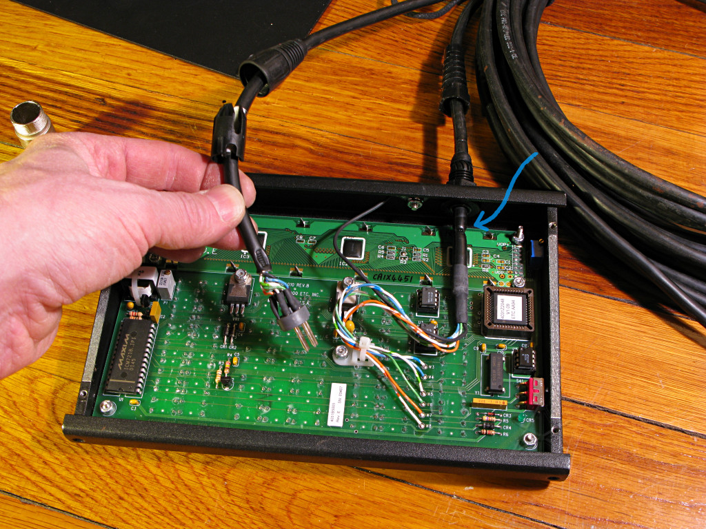
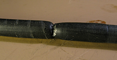
Connections in question: part of the tether wire leading up to where it gets
soldered straight into the RFU's innards, and the XLR-6.  Now, note the area
around the blue arrow.
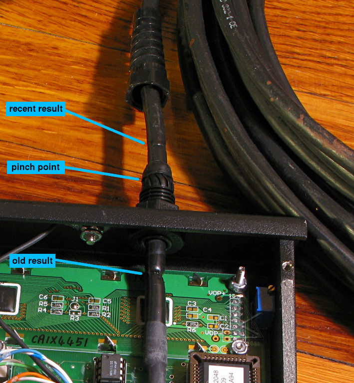
The HEYCO strain-relief and cable entry gland is a pretty good one, but it does
tend to pinch the wire pretty hard in one place right where all the little
plastic fingers converge once the tail piece is screwed on.  The long-term
effects can be clearly seen at the "old" area, which had been slid farther
inside the case a couple of months ago in the effort to alleviate flakiness.
That much bite isn't really necessary, so I had put way less pressure on
things at the "new" point by not wailing down so hard on the clamp collet.
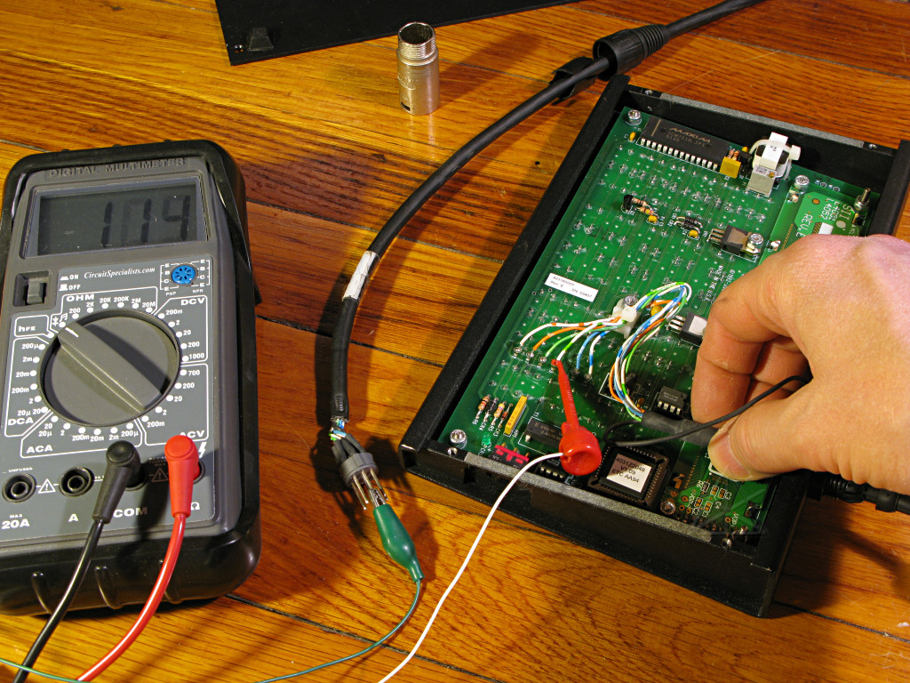
First, try to find what flaked out this time.  Everthing actually appeared to
be intact except for the white-green wire, which showed intermittent on the
continuity-beeper when the old pinch area was wiggled.
Removing six nylock nuts allowed the RFU board to come up off its standoffs
and flip over; not much to really see on the keypad side but I wanted to make
sure I could see where the wires came through it.  Plenty of room for ends to
poke out a little.  Long story short, I did what I set out to do -- pushed the
tether wire farther in through the gland, cut off the bad piece and re-stripped
to solder in new connections.  It was tempting to try re-engineering the strain
relief mechanism a little to do more on the inside of the box, but didn't want
to go too nuts on it.  The XLR-6 connector end was also pinched down a little
but seemed electrically fine, so I left it as is.  After all this the RFU was
functional once again, and put back in service.
So, time to figure out what went wrong, if possible.  Wire breaks inside
insulation are one of the most maddeningly subtle problems to diagnose just
because of their intermittency and position dependence, but here I have a
pretty narrow search field given what I already knew about the cable.  And
a good excuse to play with the new camera's macro capability.
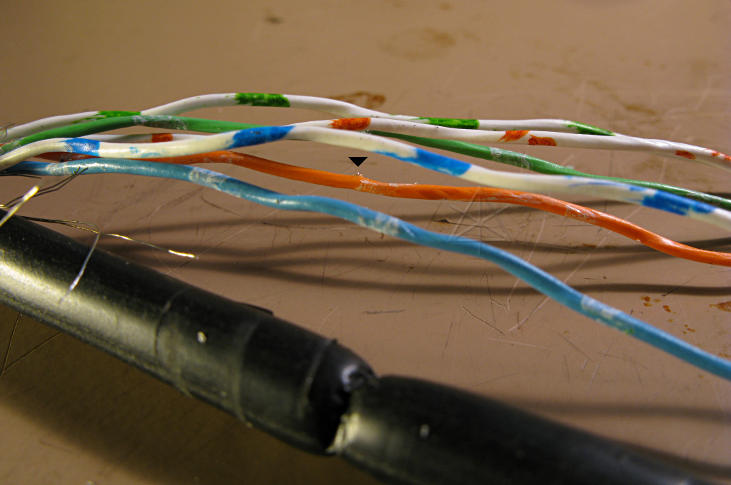
Once the outer jacket is carefully slit back and the shielding removed,
the inner wires are exposed.  I can't see anything obvious yet, although
there's a rather suspicious bit of metal actually poking out through the
side of the orange-white wire's insulation [little black triangle].  But my
problem had been observed in the white-green, so let's check that first...
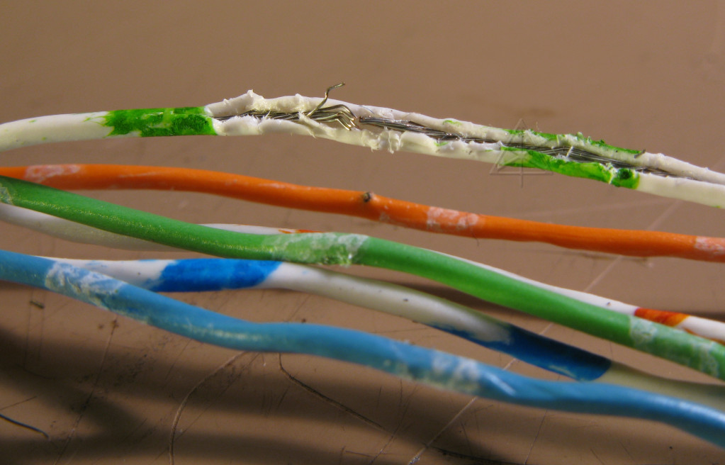
Slitting that one tiny wire open without disturbing the conductors inside too
much is a fairly painstaking, head-magnifier-needed task, but with a rewarding
result.  There's the break!  Totally impossible to see anything outside the
insulation, even though the wire strands are bent quite a bit.  Interestingly,
my slitting job has run along a bit farther than I thought it would need to in
finding the problem.
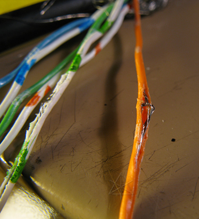
Similar investigation of the orange wire shows about the same condition, with
perhaps one strand remaining in loose contact with the other side [and that
quickly separated once moved too].  The piece poking out of the insulation
had evidently done so due to the crimping and buckling that happened inside.
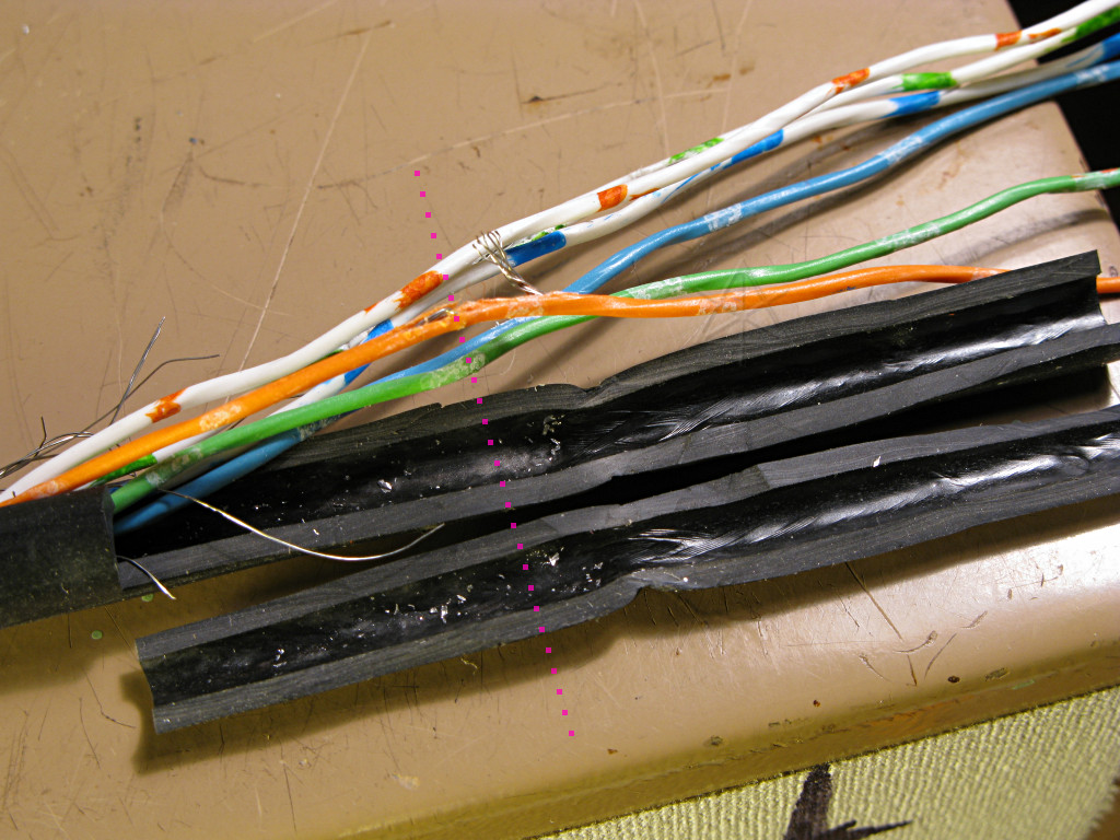
Okay, so where did it happen?  Here's the cross-section of the affected area,
with the inner wires pretty much lined up again as they sit in the jacket.
Interestingly, the wire breaks [pink dotted line] don't line up with the
pinched point, which is why I had to slit them open farther along to find the
spot.  There's a strong impression of the shield braid inside the jacket where
the gland had come down on it, but the jacket is quite thick and isn't actually
punctured.  So the breaks appear to have happened just slightly *outboard* of
the pinch, under the strain relief in the gland's tailpiece.

I called ETC a little later since their "improved" website is a useless
swamp of script-driven garbage and I couldn't find anything on it.  They're
much more helpful in person, and one of their techs was kind enough to read
me the RFU pinout:

     5         1	1 -- Data (+) to RFU, white-blue
    *     6   *		2 -- Data (-) to RFU, blue-white
         *    2		3 -- Data (+) from RFU, white-green
     *       *		4 -- Data (-) from RFU, green-white
    4    *  		5 -- common, white-orange
          3		6 -- +12V supply, orange-white

[looking into the female connector on the back of the console]

This helps explain both problems.  Originally it was an RFU power issue -- it
would blink in and out depending on how the tether cable was held near the back
of the unit, which was most likely the issue with the orange-white wire.  I
can't imagine how it managed to hold together, especially supplying *power*,
for a couple of months after simply shifting the cable inward.  Then the wire
I found broken this time was keeping the RFU from talking to the console via
"data from RFU", which is exactly what I'd observed.  Now, the orange wire
could have just as easily poked out and hit the shield or penetrated its paired
"common", etc and shorted something instead of just going open.  According to
ETC's knowledgebase, the 12V line is fused inside the console at 1.6A but
that's still enough current to get a nice toasty little event going on
downstream.

And the ETC guy said "yeah, we always get problems with those cables --
y'know, someone runs a Genie lift over it, they get kicked around..." which
is probably one major reason they have wireless RFUs out for these boards now.
What I've observed is that the area just where the wire comes out of the RFU
tends to get twisted around a lot, especially when people invariably use the
cable as a carrying handle -- and even though the strain relief tail tries to
keep it from bending too far, it seems like the inner wires can't shift
longitudinally at the pinch point and wind up receiving *compressive* force
just outboard of it, causing them to buckle sideways.  We're talking *very*
small strands here, but even those can eventually work-harden and crack.
Having a little less pressure clamped down on the jacket may actually help,
as long as that doesn't allow the other potential problem of the whole wire
twisting around inside the case.