
The bloody thing was *leaking*.
A still picture can't really show what I discovered, but this short video can.
| We were almost done. The correct HRV still had yet to arrive, and I would be doing other minor ductwork fixups around the house myself later. But in the meantime I had this new heat pump system to play with, although in June there's generally not a lot of heating or cooling needed so actual capacity measurements would have to wait a while. I could nonetheless take a look at all the many settings and service modes whose descriptions in the manuals had intrigued me so much. I also wanted to check various fasteners for stripped threads and get some anti-seize onto some of what would be the more frequently-accessed screws, making a mental note to caution the installer to only use hand tools on them from now on as he also had that industry-wide pernicious tendency to grab the impact driver by default. |
A disturbing discovery
|
|
So I pulled the cover off the outdoor unit to poke at its buttons and check
that its various settings were still the factory defaults, and it was a
good thing I took the time to look in here. Because human vision is so
adept at spotting movement and changes, I happened to notice a tiny bubble
appear on top of the larger flare fitting, move along the threads a little
way, and disappear. And this kept happening. The whole fitting was
covered in oil, and it was oozing down into the pipe insulation.
The bloody thing was *leaking*. A still picture can't really show what I discovered, but this short video can. |

|
I immediately sent mail to the installer, hoping he'd read it before
arriving onsite for the wrapup work and bring the appropriate gear to
fix this. Fortunately he saw it in time and showed up with a jug
of refrigerant that morning. [Which, I found out later, he should have
been bringing to bear on this system anyway.]
I postulated that my test of heating mode from a couple of days back had swapped this particular pipe over to the high-pressure side and that had probably triggered the leak to start leaking, but more importantly that if we had done a proper pressure test in the first place this would have been found before it became a problem. He still tossed this off as extra procedural fluff that wasn't needed, despite evidence right here in front of him that it was. |
|
Then he did something that's not recommended or even documented at all in
the manuals but is a common procedure on other units -- a pumpdown. This
is a hack that lets the unit compressor push most of the refrigerant
into the condenser and store it there behind the service valves, allowing
the lineset or indoor parts to be opened up and serviced without having to
replace the entire charge. It is usually done by closing off the liquid
line and
manually engaging the big electrical contactor that makes the compressor
run until the low-side pressure drops to near zero -- except that this unit
doesn't have the obvious contactor so we had to kludge around that.
He had me go inside and call for high cooling, closed the liquid valve and let the lineset pressure drop down to about 40 PSI, whereupon he quickly closed the other valve and then simply yanked the disconnect to shut everything down. Said that if you wait too long, the unit shuts down on an underpressure alarm and loses the pumpdown back into the lineset. So at this point, in theory most of the refrigerant was now stored as liquid in the condenser unit's coil and other plumbing. According to Daikin, this is a bozo no-no on these units and the proper procedure is to put the unit in a special mode that fully opens all the internal valves, and then recover all the refrigerant out of the entire system before trying to work on it. But he figured on a leaking system that he hadn't added any extra juice to the system in the first place, it could all be put back into the condenser where it had originally come from at startup. |

|
It seemed to work, and a relatively minimal amount of remaining gaseous 410A
just went pfffft! off into the atmosphere as he loosened the flare nut.
There is always a little bit of inevitable refrigerant loss when dealing with
as pipes and fittings like this, but the industry is mandated to keep that
to an absolute minimum these days -- even with the newer "environmentally
friendly" refrigerants like R410A. Trouble is, the new refrigerants are
much more sensitive to added moisture, air, or crud inside the systems
and one *really* needs to be more careful than ever with it all.
Unlike this fellow. |

|
Anyway, we both looked at the flare itself and despite its having been done with his cheap tool it looked okay to both of us so he put it back together. Still without any sealant or lubricant like Nylog Blue which appears to be thought of highly around the industry as a good leak preventative. With the difficulty he'd had bending the large line, including the final 90 up to this point, it's possible that the flare wasn't quite squared up to the valve fitting the first time. |

|
This time, however, he back-torqued the valve body with a second wrench
while tightening which he hadn't bothered to do the first time. This really
is necessary, because the thin bracket the valves are mounted on just bends
and can't resist the necessary torque -- which in the case of this large
flare, the spec is 50 foot-pounds. That's almost up into the same
territory as lug nuts on a car, so it really does need to be tight and
with weenie little crescent wrenches, that takes a lot of force. He
didn't have a torque wrench [another recommended technician tool],
but pulled on it to the trembling-arms point and called it good.
He then tried to perform a pressure test, but his nearly-empty nitrogen bottle ran out long before getting the system up to the recommended 450 PSI. Way to come prepared for a job, dude. Wait, it gets better. Since the right model of HRV had also finally arrived that morning, after bleeding off the pressure he started the lineset vacumming down again and we went inside to hook up the ventilation ductwork. |

|
We unboxed the HRV and mused, "wow, that's tiny" -- and remember, this was
the one with higher capacity than the retrofit contractor had originally
suggested. The installer's primary experience was with the horizontal-ducted
type which usually hang from the joists on chains and are a bit bigger and
klunkier. Since I freely acknowledged
that I was likely going to rework all of this later we did sort of a
quick-n-dirty placement job blocked up on a few of his cut-offs from building
the air-handler frame. Even with the vertical duct collars the elevation
on blocks is needed to leave space for the drain tube barb fitting
underneath, which would eventually have a hose into a condensate pump
on the floor.
He cut the ducts to fit, more or less -- actually came up a little short on a couple of them but I was going to raise the unit even more anyway so that didn't matter. He also left me several six-inch hard duct elbows to get cleaner, less restrictive bends in the directions the ducts headed away from the unit. |
|
I was fine with sort of a half-done installation on the HRV because we
both understood that I'd be moving the connections around and playing with
all of this later.
I also temporarily hooked up the controller, nominally slated to go
upstairs somewhere, right next to the unit on a short wire so I could
explore what it does. I needed the fancy "EDF5" type controller for the
best versatility in fan speeds and timed cycles, so that's what we ordered.
It connects to the HRV on a simple two-wire interface that again, just
like the heat pump system 'stat, carries power and data.
We went back outside to check on the vacuuming, and he realized that he wasn't actually getting a good vacuum at all and that the reason was that his pump was really low on oil. Vacuum pumps need a proper level of oil sump to fully seal the running parts and achieve good suction, and as a tiny bit of the oil always gets pushed out with the discharge it needs to be kept topped up -- something not always done in a timely fashion on a piece of kit banging around in the back of an HVAC service truck. It seemed like the installer was also suspecting leakage in his own test hoses or fittings, possibly influenced by a half-snide related comment I had made earlier in the day. In any case, he decided he needed to take about a two-hour break to go shopping. This was my opportunity for some initial ventilation system testing, part of which would involve swapping the flex ducts around particularly to mess with the Cape backdraft damper. |

|
With a quick duct transposition inside, I could create an inward flow at the exhaust duct to test the damper. This is how it closes: the membrane sort of falls in on itself, confined by its attachment along the bottom of the duct, and seals pretty tight. Simple and effective. |

|
This is what it looks like open, with normal airflow outward. The top edge flutters a little but it's silent and quite non-restrictive, especially when six-inch ducts are a bit oversize for the normal expected airflow. |
|
Okay, so here were two substantial tubes right into the building envelope
that would frequently have really cold air passing through, and the next
question was this: what effect would that have on overall insulation
value? In theory, it's easy to calculate: Assuming that the problem ends
at the HRV and we don't consider the "tempered" inside ducts,
the fiberglass blanket around the 6"
duct is about two inches thick. Calling it an average radius of 4 inches
at the center of the insulation over maybe 18 feet of duct yields an
effective wall area of 38 square feet. This would be like adding a
roughly 6 x 6 foot section of wall to the house at R-8 instead of the
nominal R-26 the main retrofit would bring. But the longer exhaust
duct wouldn't run at exactly outdoor temperature, since the heat exchange
in the HRV isn't perfect and to complete the picture one must also
calculate heat gain/loss in the exchanged air volume itself and factor
in the HRV efficiency rating. Still, in comparison
to the building's 2300 or so square feet of above-grade surface area, the
duct walls of these short runs are down in the noise. Why worry about it
in the first place? No outstanding concerns, it was just yet another in
the series of informal HVAC engineering exercises I was having fun
putting myself through.
A less than satisfactory wrapup The installer finally returned, bearing a bottle of vacuum pump oil, a new set of gauge hoses, and his favorite ol' analog Yellow Jacket manifold gauge set. Still no real micron gauge. His pump took the *entire* bottle of oil just to come up to the correct level, while he admitted that he really hadn't paid proper attention to this for ... how many other jobs, customers, and perhaps insufficiently-vacuumed systems before this one?? but with that all fixed and happy now, he once again hooked up to the valves and started suckin' 'er down. With the analog gauges in place now instead of the digital widget, we could at least watch the low-side needle plant itself pretty firmly into the negative region. While that was going we went back inside for the final installation step, bolting in the resistance heating module. [More on that later on.] That was easy, as it's two power connections and a control plug. The headscratching part was figuring out how to configure the system's "field settings" to tell it that the heater was installed. I already knew how to do this from reading the manuals but I figured I'd let him sort it out his own way, in which he again made it clear he hadn't done this particular variant of system modification before. Well, not that the user-interface of the remote controller upstairs makes it a straightforward task in terms of button presses. But we got through it and I figured that I'd just have to wait for cool weather to actually put the heater through the testing paces. Back outside to the condenser, which we figured was about as vacuum-dried as it was going to get that day. He pulled off the pump and let the refrigerant back out of the outdoor coil, and the next problem was figuring out how much had leaked out. With a system with feedback-driven computer control that's able to adapt well to a large range of improper charge, how do you do that? Not by target subcooling charts, that's for sure. Well, our fella had another somewhat old-school albeit possibly handwavey idea. We started up the system in high cooling mode again, and he simply let new refrigerant into the liquid side in little squirts until the low-side pressure settled in around 140 PSIG, corresponding to about 50 degrees on the R410A saturation curve. Total guesswork -- he didn't even check what the actual temp of the indoor coil was at the time, but at least it got a little more refer into there. Said it "took about a pound", called it done, and buttoned everything back up.
This felt like a total hack job to me but I reined myself in and tried to
not stand there and tell the guy how do perform his "been doin' this for
a lotta years" job. I figured I'd ask around later and find out just
how hack it might have been, and the raw evidence can be found in these
two forum threads:
As the back of his truck retreated into the distance that afternoon with my final check inside, I realized that I would probably never see him again and likely had very little recourse as far as this commissioning laxity. I'd already bounced some of these doings off Daikin's support engineers who had agreed "ooh, that's not good" but there was very little they could actually *do* about it -- they train contractors, but don't control them in the field. It began to fully come home to me what one of the hvac-talk guys had said, how the residential HVAC market is such a joke. Mind you, on the overall system he'd basically built what I specified and had done a pretty good job on the ductwork and adaptation inside, so it certainly wasn't all bad. But as far as system startup and long-term reliability, about the only path open seemed to be finding another tech who would actually give a rat's ass and having them work the thing over and give sounder advice. Which I eventually did, detailed later in the saga. For now that could wait, as the heat-pump system was for the most part working [and presumably not leaking anymore] and I already had a whole slew of other post-contractor fixups that *I* wanted to do. |
HRV Hacks

|
I needed to really familiarize myself with the HRV. It was ultimately going
to be my substitute for an air-leaky house, and keep me from dying of
CO2 poisoning in a swill of my own miasma. I detached all the ducts
and took it off the table to spread out all its parts out on the floor
and have a good look. It's fundamentally really simple -- the exchanger
core and a couple of fans in an insulated box. But already I was noticing
some aspects that needed to be fixed.
|

|
The first thing to go was the lid switch. There's no need to turn off the
fans just because the unit gets opened up -- if I want it shut down
I'll do that myself thankyouverymuch, and the switch was making
a bump in the sealing surface that already looked like a minor air leak.
It turned out that the black wire from the line cord to the switch would
reach down to the control board and connect straight onto the AC-hot power
supply tab on it with no mods needed to the wiring at all, so it was as easy
as the move shown by the arrow. A quick piece of tape to fill in the
mounting hole, and that switch was outa there.
The control board in here is fairly straightforward, and basically clicks a few relays on and off for fan speed and the defrost flap motor. Its hardest job is probably to maintain serial communication with the external controller. |

|
This model ventilator has six-inch duct fittings which actually seem a little oversize for the expected airflow, but maybe here's why: the way it's built blocks a good half of both supply-sides with crap. The white foam is insulation around the central core compartment, and the damper flaps are presumably for balancing airflows but there's only one of them installed. It's a little mystifying why Fantech didn't just design the outer box a couple of inches longer to avoid having the internal parts conflict with themselves like this. |

|
I realized right away that the [!one!] balancing damper would be completely useless, as I've got external dampers at the fittings where the HRV interfaces to the rest of the house ductwork anyway. With the collar taken off the flaps were an easy snap-out. I also cut back the foam at a 45-degree bevel on both output ports in the hope of making a slightly nicer transition for flow coming off the fans below. A couple of other ports needed obvious and quite superfluous restrictions carved away too. |
|
The backward-curved fans don't really have a shaped volute around them
to direct airflow, but with the cover closed up the chambers they run
inside seem to pressurize and exhaust well enough out the delivery ducts
[esp. after being optimized a little more]. I played around with the
controller some, figuring out how to set speeds for various overrides
and the cycle timer, and then put the HRV back together and mounted it up
on taller, correctly-sized and more stable blocks on the table. This
let the cold-side ducts reach it better and keep the insulation continuous
all the way down to the outer collar and outside of the box.
The defrost damper basically switches between normal outdoor-air intake and pulling from the basement air right by the box. It actually closes off the intake reasonably well in standby state, preventing what could otherwise be a significant infiltration source. Its actuator is simply a little low-power AC gearmotor turning against a spring, and once the damper is swung all the way to the defrost or "outdoors closed off" position the motor stalls against a stop while still under power and thus sits there and gets rather warm. No provision is made for lowering the current through it once it's done its brief little job, so I expect that'll be one of the first parts to fail. Bad design; this would have been easy to run through a phase-switched triac or something. I floated several of these issues to the support folks back at Fantech, which they hopefully took in the right spirit as product-improvement suggestions. Some of this stuff is really basic. In return they were pretty helpful later when I was trying to figure out some of the integration connections between the HRV and the air-handler. The HVAC installer had left me almost a whole bag of "duct straps", aka huge long zip-ties, since he knew I'd be making changes to various hookups. These are actually hard to get tight enough onto flex duct so it actually stays on a smooth fitting. I later determined that a twice-around cinch with the black theatre tie-line I have plenty of with a taut-line hitch actually works way better and is completely reuseable. |
A/C hacks

|
The HRV wasn't the only area needing improvements; next was to tackle the main heat pump system. With the installer gone and taking his strange control-side ideas with him, I made fairly short work out of pulling his Romex "data line" and re-running it with the type of real stranded wire Daikin suggests. I've got lots of this stuff kicking around from my serial-terminal work of yore. After that was put through the pipe, I could finally foam in the lineset penetration for real and get all that sealed up. |

|
In the process of re-running the data line, I added a switch to quickly
make or break the connection between indoor and outdoor units. This was
to entertain a theory -- that if the indoor air-handler lost communication
with the outside and still had a heat call, I was hoping it would revert to
heating entirely off the resistance element in a sort of "emergency mode".
Why would I want to do that?? To be able to *measure* actual heating energy
in terms of electrical input at the metered subpanel, rather than having
that all thrown off by some unknown and unmeasurable coefficient of
performance from the heat pump. In other words, to heat the "expensive" way
for some quantity of time to collect accurate heat-loss figures for the
new envelope, as I could no longer time the runs of the oil furnace.
With the switch I could in theory leave the outdoor unit powered up,
keeping its compressor warm, but convince the air-handler that something
was wrong with it. It was a lovely theory indeed, but in the long run
didn't turn out quite like I expected.
The new data connection went through the white terminal block near the bottom, to also bring out a tap to couple of banana-plug connections for easier signal monitoring. |

|
The signaling itself appears to be short bursts of differential data
applied over a 16V DC bias, at about 9600 baud. The bursts are relatively
infrequent, and it takes a few minutes for the system to notice and
respond appropriately to either opening or closing the data-line switch.
Because the system is powered from 240VAC and most plug-in scopes are internally grounded, I had to do all this observation with two probes in differential mode. The low-voltage power supplies inside are floating, and I didn't want to simply short some part of the system to ground. |

|
I pulled the auxiliary resistance heater, aka "big toaster", back out to
have a better look at it. Simple and brute-force. It has its own relay
and overtemp protection widgets built on, using a simple 24VAC output
from the main control board to fire it up.
On the heater plate is where I observed the Goodman label, my first hint that the whole unit might be from them too. Knowing that now also helps explain why some things about the unit seemed a little odd, such as the lack of a return-air temp sensor which most other Daikin-made indoor units seem to have. However, it gets even more confusing: much later on I found out that the heater itself is made by Warren Technology out of Hialeah FL, same town as the refurb electric meter company. |

|
It turned out to be quite easy to apply power to the heater under any conditions -- its relay has generous double quick-tab connections at every point, so firing up the toaster is as simple as moving one wire to the other side of the relay and turning on the switch on the outside of the unit. Another one-wire hack and we've created Fire Hazard # 3, because one must also manually make sure the fan is running any time the heater is enabled to carry that three kilowatts of heat *away* from it and the surrounding ductwork. |
|
There's actually a good reason to want to run the heater while the unit
is in cooling mode sometimes. It's called dehumidification. Sometimes
in wet but not too hot weather we want to dry the indoor air but not
chill it down too much, and the way that's normally done [including by
generic dehumidifiers] is to first cool the air and condense the water
out, and then reheat it back up to original temperature which, obvious from
looking at a psychrometric chart, delivers a lower relative humidity.
Mind you, most dehumidifiers have the hot-side coil as the last thing in the overall air path so that's how the heating is done most efficiently; we don't have that choice here but running the heater which is downstream from the coil can have the same effect -- again, probably the expensive way to do it, but I actually used this hack a couple of times over the rest of the summer just to knock some indoor humidity down without freezing my ass off when it stayed stupidly soggy outside for several days. | |

|
Because the air handler and aux heater both run from 240VAC circuits, the installer provided a 240VAC condensate pump. For some reason the electricians had wired the outlet for the pump to the *heater* circuit instead of the main AHU circuit, which doesn't make any sense as the circuit for the heater is usually shut down when the unit is in cooling mode. So I decided to open up the box and rewire the whole mess with the pump coming off the air-handler circuit, cleaning things up and eliminating a couple of excess wire-nuts in the process. |
ECM games
|
I tried to do some airflow measurements with my small anemometer, for
example by taking an "averaging scan" over the filter-box opening with
the cover and filter removed and the return duct from the house blocked
off. What I came up seemed quite a bit lower than what the listed spec
for the unit is, and I'm not sure why -- must have been some
directionality effect going on, or the head area on the anemometer
interferes with itself too much, or something.
But part of this screwing around involved researching the behavior
of ECM blower motors,
which this has one of in the "ECM 2.3" version. Yes, brushless
electronically-controlled air-handler fan motors actually have versioning
that has progressed over recent years.
This is because most of them are made by the same company, which is a
confusing conglomerate involving GE, Genteq, Regal-Beloit, and a fairly
unfriendly website called
thedealertoolbox.
Bottom line is that ECM units are far more efficient than old-school permanent split capacitor induction motors, as they drive a three-phase permanent-magnet motor at fully variable speeds using power transistors. Gee, does *that* sound like a recurring theme?? Long bit of research shorter, the controllers bolted onto the backs of these motors actually get factory-programmed with different torque and RPM curves that allow them to maintain constant *airflow*. That means as ductwork becomes more restricted, the blower will spin faster and harder to make up for it and try to keep the same amount of air going through. The extreme case of this can easily be witnessed by blocking up the whole return path, which causes the motor to go from its normal gentle almost-silent operation to more like a screaming jet engine at high RPM. Just by restricting airflow, not even changing any fan settings. The motors are also designed for direct integration into furnaces and air handlers, taking various commands and speed controls into a low-voltage interface at the same 24 volts AC that thermostats and burners and everything else uses. So the "fan" and "heat" and whatever terminals from a 'stat can be wired straight to the blower motor and not only enable more efficient and more stable operation, but eliminate the need for extra fan relays and such in the process. Feed these things power and control, and they just work. They even have built-in post-run delays before stopping, to allow for cooldown and the like, and capability to accept some simple diode logic to select different speeds via half-wave control inputs. There's a comprehensive textbook (pdf) on all this stuff at Prokup Media's training site, and numerous other findable online references. Speaking of post-run, one of the first things I noticed about the air handler was that any time the system was set to "on" at the controller in heating or cooling mode, the fan was running at the selected speed -- even when it wasn't actively heating or cooling. This is dumb, especially in cooling mode, as the last thing you want to do is stop running the compressor and let the indoor coil go warm with all that water still loaded up on it -- thus blowing the humidity you just worked to capture right back into the house. The fan in a cooling situation needs to STOP and let the coil quietly drain down into the catch pan. Long story shorter on *that* is that Daikin's application-engineering folks were kind enough to send along the "seekrit field settings" PDF which detailed how to configure the fan to go OFF after heating or cooling setpoints are satisfied. Yep, two different settings I needed to go up to the controller and wander through the field-settings menu to set -- 12(22)-3-03 for heat and 12(22)-6-03 for cool, specifically stated here in case you're up against the same problem. Probably works across a large cross-section of Daikin units, as field settings seem to be fairly consistent among them. In this particular AHU, the ECM fan itself is programmed with a 3-minute off delay, which is just barely short enough to extract the last bit of residual "cold" from the coil but not run it too long above dewpoint. It'll do for now, especially as reprogramming the ECM involves some proprietary piece of gear that almost nobody has. This clinched one of the reasons that return-air sensing wouldn't have worked here. Dry-bulb temperatures in the basement and thus inside the air handler without the blower running could be very different from upstairs, which would totally wack the system's idea of demand. One of the nicest features about Daikin and the other inverter-drive systems on the market is that they can ramp down their own compressor speeds and thus working capacities as they approach setpoint, particularly in cooling, and continue to run in a low-power but very efficient way for quite a while longer to actually reach it. Sometimes with a high latent [moisture] load on low fan, this one will run for three or four hours at one degree below the controller setpoint while still pulling lots of water out of the air, rather than cycling on and off like typical old-school units. This is worlds-apart better for humidity control. They can do this because of all the temp sensors attached to the pipes at either end of the coils, and control their electronic expansion valves to run at precise levels determined from observed conditions. The pressure's on
*Note: Some of the following paragraph is wrong, at least in a static setting with the system not running and equalized. Because: refrigerants in a saturated mix do not actually change pressure based on liquid volume. That's what's so magic about them. *Any* liquid present makes a refrigerant at rest simply obey the pressure/temperature chart, regardless of relative quantity of liquid or gas. There are even "trick" questions on the EPA 608 certification tests that cover that. In a correction applied around 2020, I have struck out the erroneous information. Having taps into the pressure sensors is still useful, however, especially in heating mode where both sides of the physical lineset become "high side" and there's no way to know suction pressure except from a tap just before the compressor. Which the low pressure sensor is.
In further wandering through various Daikin system documentation, much of it not even pertinent to my specific unit, it dawned on me that I just might have the next best thing. The condenser unit has *pressure sensors*. Not just over/under pressure limit switches -- it has them too -- but actual sensors to read high and low line pressure back into the control board in a nice linear fashion. The schematic showed right where they hook in, too: simple 5V power, ground, and sense leads. This demanded immediate investigation. |

|
It turned out that the pressure-sensor leads run through a couple of small connectors conveniently right at the front of the unit, so without even having to take anything apart it was voltmeter and differential-scope time [as this unit also runs from 240VAC power]. With both coils sitting at around 71 degrees that day I set the unit in "all valves open" vacuuming mode to make sure everything was equalized, and the DC volts between the sense wires and their little grounds seemed to match the documentation. |

|
One big hint that I might be able to read system pressures electrically
was finding a couple of pressure vs. voltage charts squirreled away in
some of the more commercial unit documentation. In particular,
this one
which isn't even hosted in the US showed the charts for R22 and R410A, but
had the curves and voltage-to-pressure transforms a little mixed up so
after printing out the page I had to draw in the extra lines for R410A.
But once I had that and filled in all the rest of the pressures in PSI
against their MPa scale, the voltages I was seeing made sense. Upon
starting the unit for cooling, both high and low sensors settled right
in at right around 2 volts each, telling me that they'd been selected
to read a nice mid-range when running in typical ambient conditions.
This was showing me about
300 PSI and 120 PSI, pretty nominal for R410A in
|

|

|
|
Clearly, I would want to monitor these signals fairly regularly. While
the sensor connectors are conveniently located they're actually not all
that convenient to hook into, so I wanted to add a more permanent
connector to tap the signal leads but not make it too bleeding obvious
that I'd cut into the wiring harnesses. After all, here I was adding
diagnostic connectors to a brand-new unit. So I pulled things apart
just enough to bury my slit-n-tap connections behind the panel where
power comes in, but running up to a third connector to sit
right next to the original pressure-sensor connectors and almost look
like it was supposed to be there from the factory. A simple adapter
could then break out the two pressure sense leads and a signal ground
to a longer wire I could lead down and safely outboard of the unit.
The relevant connectors that go into the main control board are even colored red and blue, typical colors for high side and low side. The sensors are located in the plumbing near the compressor and before the reversing valve, so high always reads high and low always reads low regardless of heat/cool mode. | |

|
As I posted to my Prius tech group later, it resembled a familiar situation -- tapped signal wires brought out to measuring equipment to gain better insight into some control system, but this time it wasn't the car, it was my heat pump. All the parallels with developing the Prius instrumentation were highly amusing. And I could easily argue that I shouldn't even have had to do this, as it would have been trivial for Daikin's control coders to allow retrieving pressure-sensor data from the controller inside the house with a few keypresses. Isn't that something that would help techs in the field too? Walk into a customer's house, punch a couple of buttons on their thermostat, and get a complete system picture without even pulling any gear out of the van, including that cumbersome and dog-slow "service checker" laptop setup. Daikin, wise up. |
|
The data-collection frenzy continued, as high humidity over the next few
days was a good opportunity to run the system and try to keep the basement
relatively dry. Instead of letting the condensate pump take the extracted
water away, I pulled the pump completely off the drain pipe and started
collecting
into buckets, just to get an idea of how much latent load was being handled.
Later I started *weighing* the buckets on the hour to quantify that, and
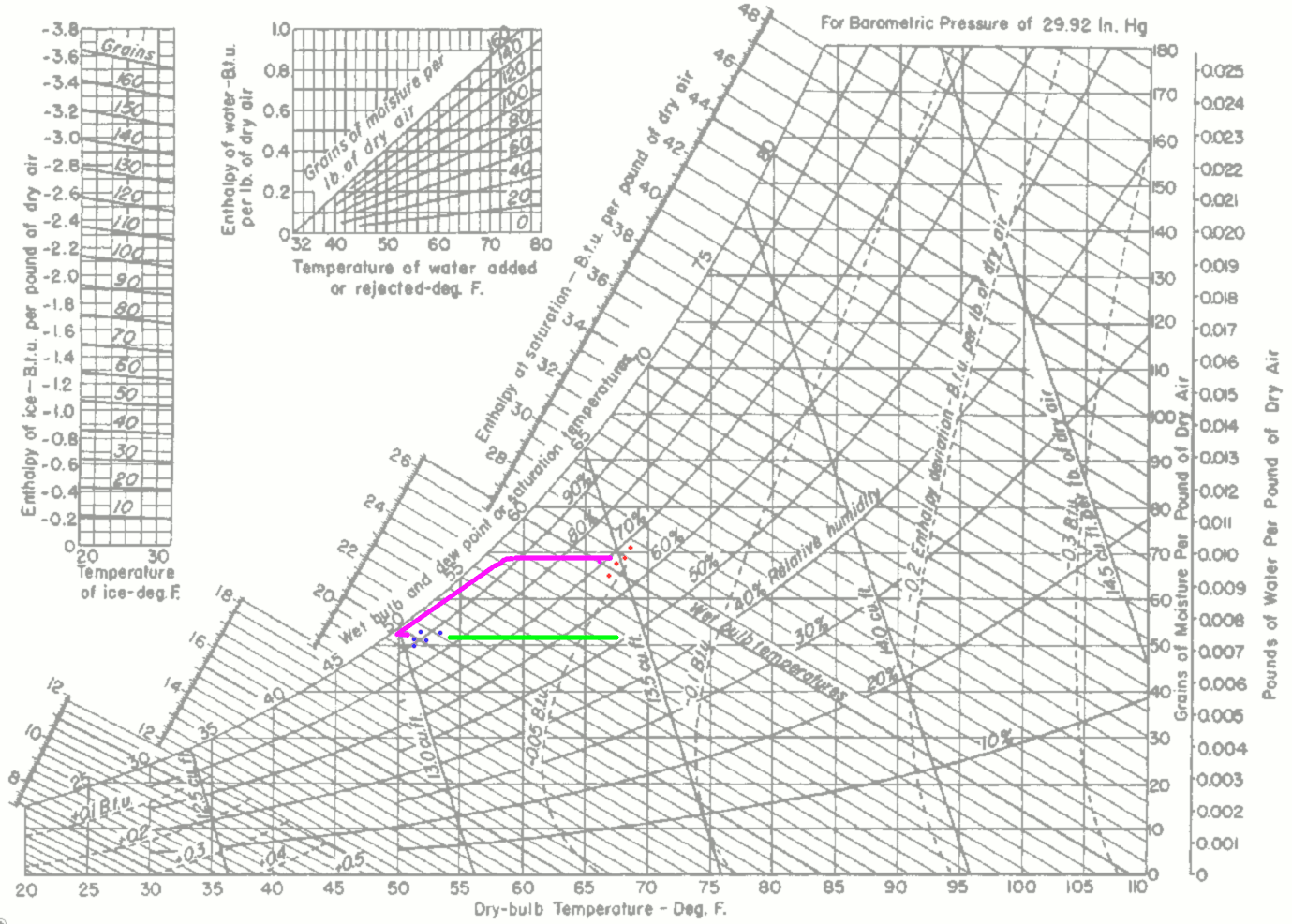
tried to figure the running capacity
on the psychrometric chart,
but there were still too many unknowns stemming from the still leaky and
not-well-insulated house. Nonetheless, it was squeezing on the order
of 4 or 5 pounds of water out of the air per hour.
It should be noted that condensate water is really nasty, icky stuff, especially from a new coil. It comes out carrying various oils and crud from the manufacturing process, and will never become "clean" since as the original guk on the coil slowly washes away, it'll get replaced with all the guk picked up from the return air that the filter didn't catch. In other words, *don't drink the condensate*. |

|
I determined that the coil and tray alone could hold about three more pints of water, which wouldn't be good to send back into the house so I was glad for the fan-shutdown fix. This determination was a result of another "magical coincidence" discovery: the hose from the wet-vac fits very nicely around the drain tube, and leaving it there running for a few minutes pretty much sucks all the water out of the tray and then to determine that figure it was a simple matter of weighing what the vac caught. This pan-emptying is useful to do whenever transitioning back into heating or fan-only run states, to make sure that the coil is as dry as possible before pushing more air through it. Dry == no mold, which is a common problem in air handlers that never get the water cleaned out of them before it turns all slimy. |

|

|
|
| High | Low | |
|
Scoping the supply current to the running outdoor unit was a bit of a
surprise -- the waveform is really ugly and full of harmonics, even at lower
compressor RPM. I really would have expected this supposedly high-end
meticulously engineered equipment to have slightly better power-factor
correction on its input, or at least a token bit of filtering to knock
some of the nasty edges off this.
The old analog amp-clamp stuck into the box was to show relative power demand, and since Daikin's firmware refuses to report compressor RPM up to the 'stat this was my quick-n-dirty way to measure compressor load. | ||

|
Even the air handler just running the fan only is pretty peaky on current
draw, which is probably a side-effect of the essentially-SMPS nature of
the ECM driver. This looks like what you get from a textbook
bridge-rectifier-into-filter-caps setup.
[The scope, just to note, came from the Frostbyte auction. Still working nicely.] |
|
In anticipation of less air leakiness I wanted a better way to monitor
indoor air quality, and ordered a CO2 monitor from
CO2meter.com. Not a carbon MONoxide alarm like most households have,
a carbon DIoxide meter so I could see just how my own breathing would
affect the air inside the house. Normal outdoor fresh air, for where we
are on the "hockey
stick" right now, is about 400 PPM and anything under about a thousand is
considered "okay" for building interiors.
The evening after it arrived I locked it and myself in one small closed room for the night's sleep, as in fact I had done any number of times over the past winters ... and managed to drive it up to about 2400 PPM. Yeah, that air didn't smell too good the next morning either. Further observation revealed an interesting partial-pressure situation, where the CO2 level inside would rise more slowly the higher it gets and opening doors or windows somewhere *else* in the house from where the meter sits started lowering the PPM anyway. Like the CO2 diffuses evenly into the entire interior volume regardless of where I am or where the meter is, and wants to equalize fairly quickly through any substantial opening in the envelope. |
Getting down to business

|
In the meantime, the Synergy guys were working toward a concrete start date for the main retrofit, and I still had a few preparatory things to take care of such as clearing any remaining items attached to the house. Instead of calling Verizon to come move the phone and fiber street drops, I decided it would be easy enough to do myself -- especially after getting up there and finding that they're really not under that much tension. But the only place they could really go would be *above* where the electric service already attached to the pole, so some kind of extender was needed. Two 2x4s in a sort of "strongback" configuration and lagged into the top of the pole would do. |

|
After that, the side of the house was completely clear of service
attachments. As an extra measure of stability I ran another piece of rope
and temporarily guyed the entire pole back to a tree since it was taking
all three street-drop loads now.
At this point I figured I'd wind up reattaching the phone and fiber to the house later on too, as there was enough length on both and I had already figured out how to adjust their self-cinching fly clamps. |

|
The FiOS fiber had to be backed completely out of the optical network terminal inside, and re-run through another new penetration pipe [made *just* big enough for the connector head] along with the phone wire. The phone box could just hang on the post bracing, and I didn't spend a lot of time fussing with that as I care far less about phone lines as I used to. The landline has become less and less useful over time and at this point I don't even answer it anymore, as all the incoming calls are nothing but spam nowadays. "Lower your credit card rate!", alarm systems, win-a-cruise, political surveys ... all total junk and that's despite being on plenty of do-not-call lists. All these sleazebags can just talk to an answering machine. |

|
I took apart the old outdoor light posts intending to get rid of them, but in the interim they turned into another piece of redneck lawn-art. This one is entitled "Expansion of Light", topped by a big glob of cured spray-foam. This particular can was still about half full but got a jammed valve I couldn't clear with acetone, so I set it on the junk pile and punched through the side with an awl and just let 'er rip until empty which is why the can is still embedded in it. |
| In most cases, it is quite possible to preserve the leftovers in the supposedly "single-use" cans of Great Stuff by cleaning the critical parts with acetone. A little dribbled down the spraycan valve stem and sloshed around and then out a couple of times, until it looks visibly clean down in there, will generally leave the valve completely clear and not gunked up with foam. A little dribble down the removed applicator tube clears that out for another day as well. But in this case the valve wouldn't fully seal again; I could hear a little hint of crackling down inside there as it continued to leak despite my best efforts. So this one can, probably out of a dozen I went through over the course of the whole project, wasn't salvageable. | |

|
In preparation for removing and framing-in of the bathroom window, I pulled most of the interior trim away and could finally see what served as sash counterweights in these. It's a helical spring with a narrow slot in the end, running on a spiral-bent piece of metal so that as the window is pulled down, the spiral forces the spring to rotate and build tension. Even when well-greased, it's not enough force to pull the window back up against all the friction in the system but allows the window to be held pretty much wherever you put it. The helix even has a slightly progressive twist, to keep the counterforce more constant through the whole travel. I thought it was a fairly ingenious and compact system, way better than the traditional "sash weight pocket" setup with big lead slugs running up and down inside the framing on ropes. This also meant that the rough framing around each window was simpler -- a plus as all the remaining windows were going to get pulled and replaced anyways. |

|
Quite unexpectedly one morning, the first sign that things were actually going to start happening arrived: a dumpster! I had actually asked Synergy to send it over a little early as I already had a substantial pile to put in it, and they came through. |

|
And the name of the disposal company is just priceless, given that we're in the Boston area. Go Sox?? Is that what I say here? |

|
I had no idea the guy was coming when he did, but by pure coincidence I happened to be wearing this shirt that morning. There was much amusement all around. |

|
The strangest things that can make a guy happy sometimes ... I suddenly
had a new toy,
and it was time to get to work. The entire end of the thing could swing
open allowing easy walk-in, and I loaded my pile in as compact a manner
as I could knowing that a whole lot more was about to get thrown in
on top.
Looking at this made me wonder just how much lead paint we were about to deal with, and I went and got one of those DIY lead test kits. I was pleased to discover that while the exterior hideous-green had a small amount of lead it was well under EPA concern levels, and the interior paint [which I'd have to worry about if I ever went to resell] has none at all. Rockin'. |

|
The contractors would need to bulk the entire house out by several inches in the process of adding the new insulation, so the stair set needed to be pushed away from it. This precast unit, probably purchased many years ago from the concrete plant right down the road, is deceptively heavy despite its hollow design -- probably weighs well over a thousand pounds, and had been solidly set on the ground here for many years. My old "hi-lift" truck jack managed to float it up just enough that I could pry it away from the house a little way, enough to get at the siding behind it. The stair unit had been jammed right up against the siding for so long, letting water seep down into the crack and get held, that here's where I expected to find some of the worst rot problems. |
|
The yellow mark on the foundation is one of several splotches of paint where
I went around and tried to mark areas where electrics were routed up inside
walls and thus locations the contractors should be careful around. I was
really trying to anticipate and accomodate everything I could for them.
It was also an interesting mental shift to start perceiving so much more of the house's exterior as expendable, giving me absolutely no qualms about destroying parts of it as long as it didn't compromise water-resistance too badly. And I could just slap temporary shielding material of some sort over opened-up areas if needed because it was all going to be academic in another few days anyway. | |

|
With the stoop shifted away I could rip out some of the rotten siding and
examine behind it. Surprisingly, the tarpaper still looked fairly intact.
A bit of ant-nest dust in here and some obvious carpenter ants wandering in
and out, but whatever was behind the paper still felt relatively solid. This
was encouraging, given how decrepit the whole bottom of the door frame
had become. This point basically never had *any* weather protection.
Further investigation could wait for whenever the old door was going to get torn out, as this was the one we'd be replacing. I didn't want to lay everything open just yet and expose it to even more weather. Besides, I had a slightly more pressing problem. |
| With the builders about to arrive in a couple of days, I disovered that yellow jackets were *once again* trying to move in at a north-side sill area where I've battled them before. It was a very small nest so far, but I noticed the flight-line as they crawled out from under the siding and headed off to find food so I knew exactly what was going on. They were building into one of the holes in the top of the cinderblocks, and there was enough of a passage under the sill to let them in there. | |

|
I hate yellow jackets. It is all too often that someone discovers a nest location the hard way -- been there, done that. That's why I've learned to look for flight paths around likely places, and that paid off here. They obviously needed to *go* before guys started tearing this wall apart, and this time instead of trying to spray upward and hope the stuff got to them I took the crowbar and simply ripped a piece of the lowest siding away in one fluid motion and then got the hell away. Now their actual entrance hole was exposed and I could nail 'em with the neurotoxins after night fell. None of this weenie "eco" hornet spray they're selling these days, which simply doesn't work even with direct application at night -- this needed the old-school Raid stuff before all activity ceased. And just in time, because trucks full of burly-men would being arriving a day or two later. |
_H* 120714