Date: Wed Sep 20, 2006 10:05 pm #18305
To: Prius_Technical_Stuff@yahoogroups.com
Subject: Boost magic on the bench
Over a year ago, Lee Hart sent in an excellent explanation of buck/boost
inverter topology, partially to explain how the motor windings themselves
can be switched to boost generated output to get above the battery rails
even at low RPM. The text of that contained the word "magic" in several
places... To restore context, he described excerpting pieces of a
three-phase driver bridge:
... consider the circuit of a boost converter.
+300v____
|____
_|_diode
/_\
____| - _ _ _ +
|_______________| | | |__________common
| one phase
IGBT |_| of motor
--||_ <--I--
| |
-300v____|
In operation, suppose motor winding current is flowing left at the
moment, and we want to boost +150v from the motor to +300v. The IGBT is
turned on; this shorts the inductor to ground, +150v appears across the
inductor, and inductor current builds up. Then the IGBT is turned off;
the inductor voltages goes to -150v and it dumps its stored energy,
forcing current to keep flowing left thru the diode and "uphill" into
the battery.
[Speaking in terms of conventional current as opposed to electrons.]
The thing I couldn't quite wrap my mind around was being able to do
this when the current originates from the motor winding itself, via an
impressed magnetic field. So I decided to go *test* this on the bench
at home and see if I could gain a more intuitive feel for what's going on.
I had the bulk of a little highish-current switching circuit and an op-amp
oscillator driver already kicking around on a breadboard, from the prototype
steering-wheel-LED booster experiment. The power side of it looks almost
exactly like the above. Funny that. The drive oscillator is stupid-simple,
running from external 12V and giving about 8 kilohertz with a roughly 60%
duty cycle. [For my booster prototype I had scrounged up an inductor that
actually *wanted* a duty cycle that long for best operation... totally by
seat-of-the-pants, don't ask.]
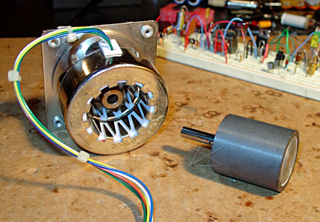
I also have several random permanent-magnet stepper motors in the parts bin,
and had found one that gives reasonable "cogging feel" when isolated and a
noticeable pulsating resistance to torque when one winding is shorted. This
one even comes apart very easily to see the rotor and how the winding poles
are configured inside. I've been figuring on throwing this into the tech-
training thing as a "fiddle toy" -- short it to feel load, hang a bi-color
LED across the leads to see AC generation, etc. Of course the guys get to
do that with the *real* Prius MGs later in the weekend, so maybe I don't
need this.
Anyway, the inspiration to put these two elements together naturally followed,
once I realized that I had all I needed to at least see *some* evidence on a
scope that this might actually work.  The circuit wound up looking more like

     gnd __||_____
           ||    _|_diode 2
         cap     /_\
              ____|         - _ _ _ +            diode 1
             |________.______| | | |_______________|/|____ gnd
             |        !            one phase       |\|
     darl. |_|    point A           of motor
        --||_                 <--I--
           | |
     gnd ____|

Since the transistor in this case is a bipolar darlington with a built-in
reverse diode, I added diode 1 to avoid shorting out half the AC cycles from
the motor and making it more difficult to turn.  With no drive at the
transistor base, the motor is effectively half-wave rectified through diodes
1 and 2 and any voltage it produces will simply accumulate in the capacitor.
I then scoped at point A, and twisted the shaft.  I got humps of a very
expected low frequency half-AC waveform, peaking at maybe 10-12 volts with
a nice snappy twist.  Woohoo, half an alternator.
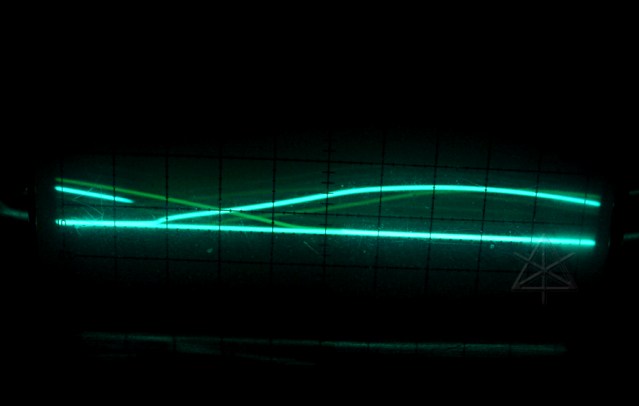 without boost
Applying the oscillator base drive produced *stunningly* satisfying results.
The same half-AC waveform was there, but on top of it were riding many sharp
peaks of well-nigh 100 volts!  I could pump the filter cap up to almost that
high before it leaked down.  The point A waveform at my 8 KHz was quite
reminiscent in shape of typical fuel injector pulses, in fact -- near
ground while my twisting built current in the winding, a tall peak when the
transistor let go of it, and then the much lower baseline voltage of the
winding thereafter as the magnet kept going past it.  It could even deliver
a little meaningful power -- when a small load of a couple of LEDs was
connected to the filtered output, I could definitely feel more loading with
the oscillator drive connected and the LEDs were brighter.  And the best
part?  I could hear that same type of "whining" inside the stepper motor
that we hear from our Priuses in strong regen braking.  Except this instance
was also pulsing as the relevant magnetic poles passed my one winding.
Still -- just like having my own little baby Prius MG2 and inverter right
there on the bench, generating unexpectedly high voltage!
 with boost
The slight flattening of the highest spikes during rise are due to the small
load of charging the filter cap; they'd be substantially higher running open.

Okay, so this is probably a totally lame physics 101 thing to you old
motor-control guys, but it's very vindicating for me.  I finally understand
what someone, I forget who, was telling me when he said "just shift the
phase of the PWM drive relative to the electrical angle of the motor".  Not
that I exactly did that here, but close enough -- now I see how it works.

Except that he might have been talking about an *induction motor* at the
time, i.e. no magnets, and I'll probably never quite grasp how trying to
do this only with reluctance could possibly work...

_H*  061015