|
Since taking ownership of this 2004 model-year car in early 2005 I've never
had its battery box apart enough to actually see the NiMH modules, and
figured that after 130K on the clock maybe it was time to just give them a
quick eyeball. While there's never been a *problem* per se with this pack,
I have observed slightly higher voltage excursions in cold weather and odd
state-of-charge variations
at high altitude.
But more concerning is that there's always been a strange chemical smell
near the vent duct next to the rear seat, making me wonder if any sort of
leakage was happening. While I already know that the potassium hydroxide
electrolyte is nearly odorless itself, I feared that if any of it was
exposed to other materials it might be causing corrosion. Thus, time
to finally have a looksee in there to at least know what, if
anything, is going on.
I also wanted to take a look at the battery blower fan and related gack, thinking to implement a switch to run it at full speed on demand. I've already got one hacked in for the main radiator fans, which help push heat out of the underhood area even when coolant isn't circulating. After a warm day of travel, the battery pack also seems to retain quite a bit of heat under the floor panel which then drifts up into my bedding for half the night thereafter, so I wanted to see if I can exhaust all that out at least back to ambient before tucking in for the night. |
|
|
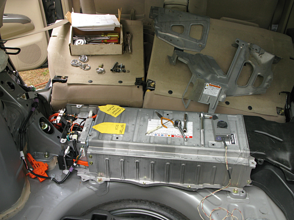
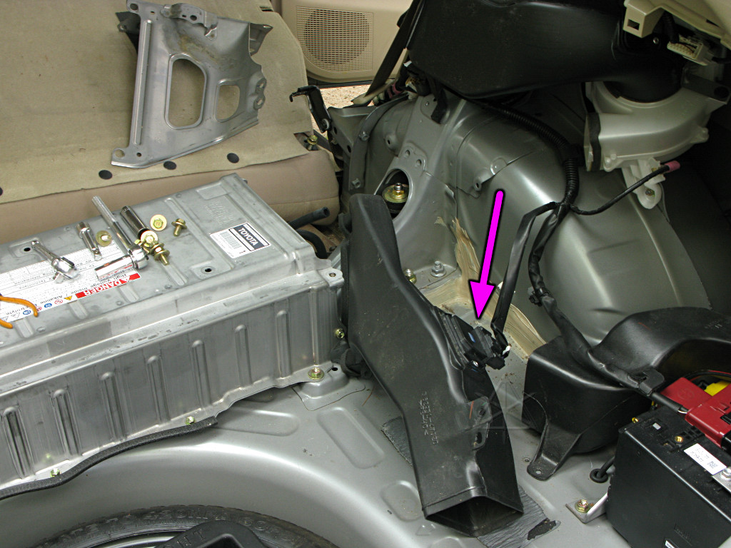
It was funny to dig back into this area and find that I'd left the old paper labels taped in from the "Naked" exhibit five years prior, from the first year I'd gotten the car. I probably figured I'd be doing the same kind of partial teardown and exhibit really soon thereafter. That investigation only went as far as the ECU and relay end of the battery box; never into the battery itself and I had never taken off the back-hatch trim panels over the vent and fan assembly side of things. This time it's all going to come out, although the battery box *itself* doesn't need to be removed from the car. In fact, the intent is to leave it in and bring it live again for some additional experimentation. |
|
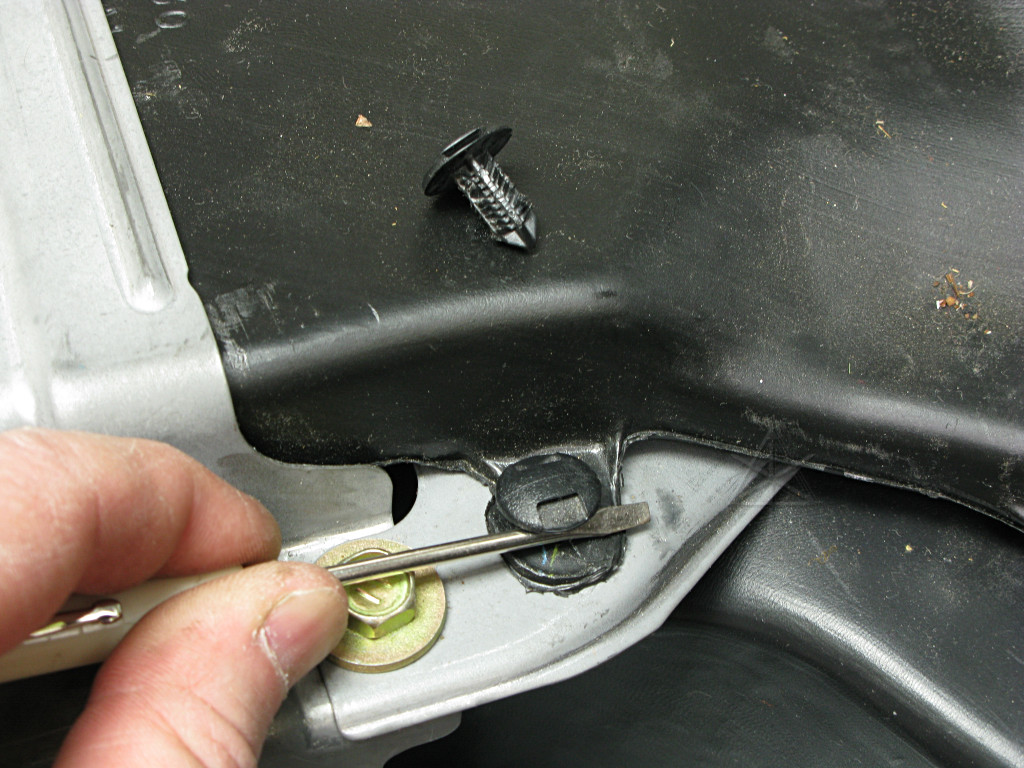
The little plastic pins that hold the ductwork in are a pain in the ass. The only way to get them out without complete self-destruction is to rock them gently upward to free up one or two of the barbs at a time, and even then the results aren't pretty. It's tempting to replace all these with sets of short bolts and nylock nuts, but so far I've managed to barely keep the plastic pins re-usable enough. The upside of flexible plastic is that it won't rattle when installed in a fairly loose fit. |
|
There's not much need for excruciating detail about battery-box or rear
interior panel disassembly here. It's a bunch of bolts in obvious places.
The rear seat cushion needs to pop out to expose access to some of them, and
later in the exploratory process it helps to unbolt the seat backs themselves
and get them out of the way too. All that is easy, requiring nothing more
than your favorite 10/12/14 mm socket set.
And common sense about electrical safety, of course. The battery *can* be lethal if mishandled, just like any other high-voltage electricity source. |
|
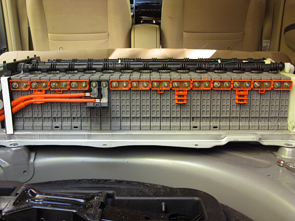
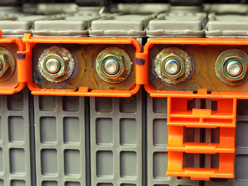
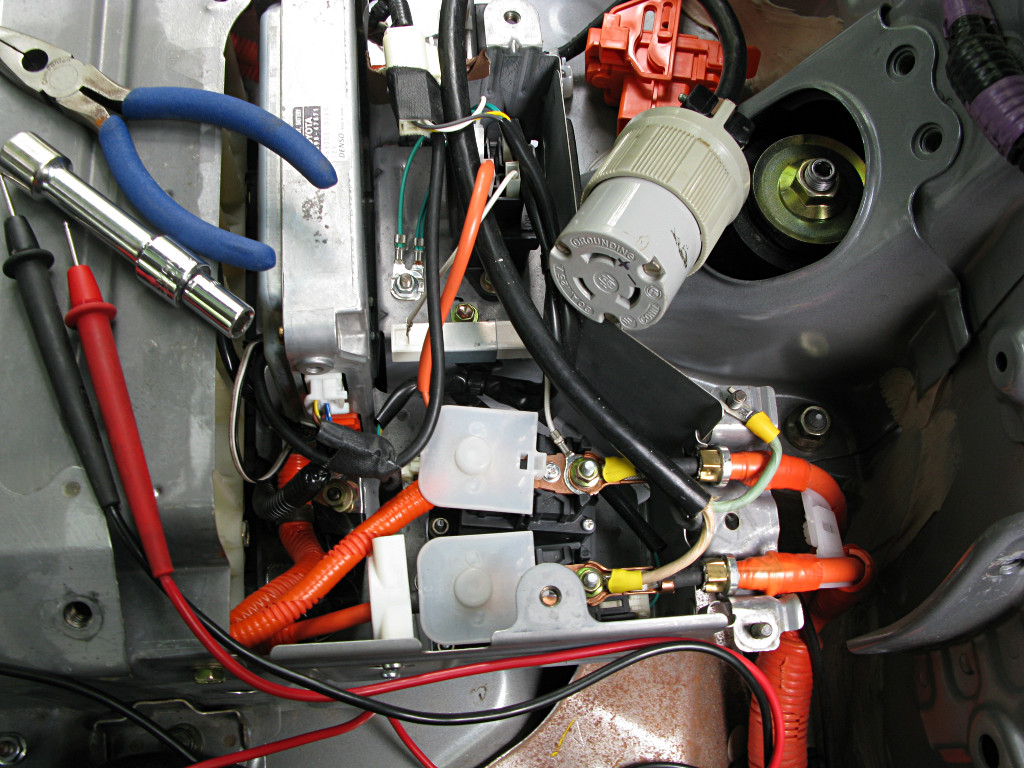
With the cover finally off and all the black plastic terminal cover pieces
unclipped, I can have a good look at what we commonly call the "bus bars".
These aren't really bus bars in the classic sense, as they don't tie
multiple points together; they're just the interconnects that string all
the battery modules together in series. The little copper strips are
clipped into convenient plastic holders that retain and protect
them as well as insulate connection pairs away from each other.
This is the rear set, toward the back of the car. No leakage or nasty corrosion visible, nor any evidence of hot spots where a connection might be loose. The bottom of the case around the module bases is totally clean. |
|
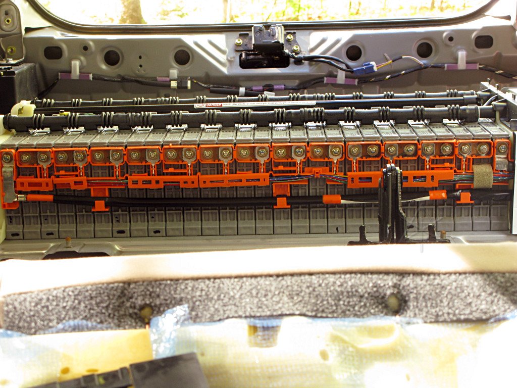
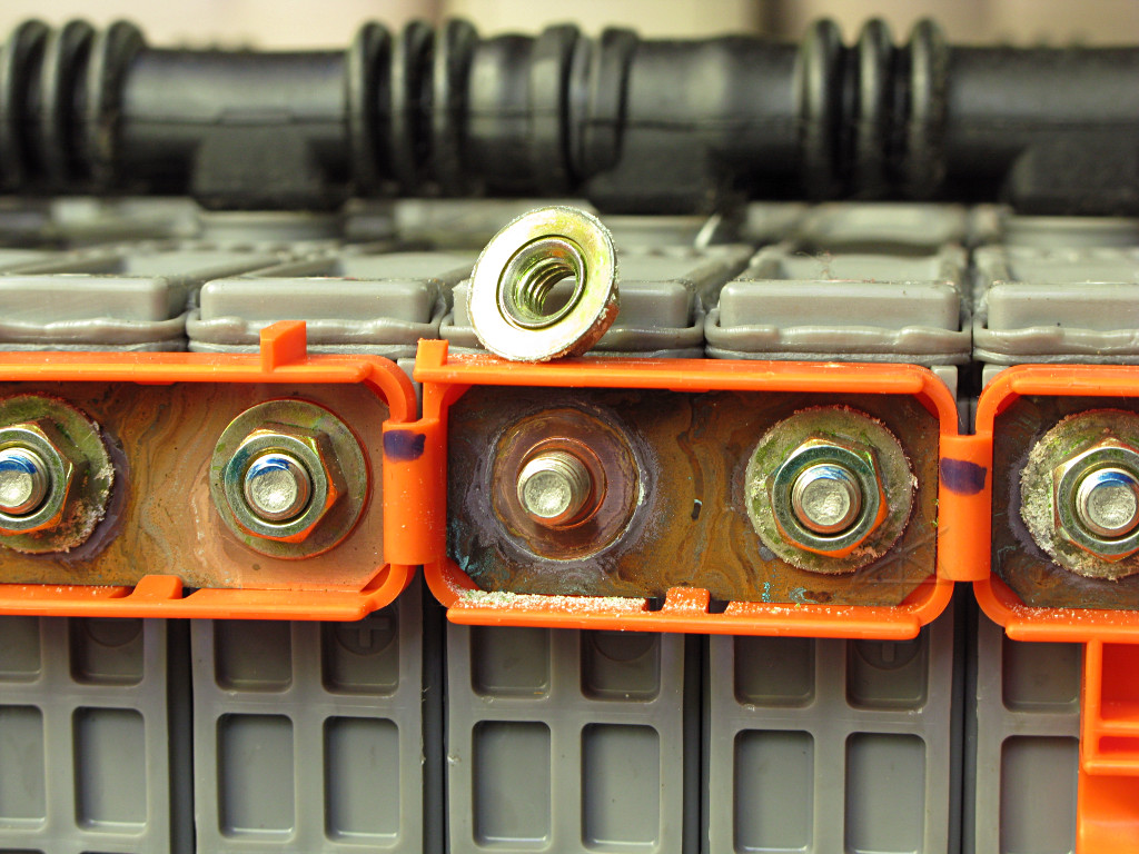
And about the same deal on the front side. So that immediately shoots down any suspicion that the smell might be coming from bad things happening in the battery box. That's a bit of a relief. |
|
There is, however, just a little white "fuzz" on many of the terminal connections, mostly at the negative ones. Not sure why, but bears some deeper investigation. |
|
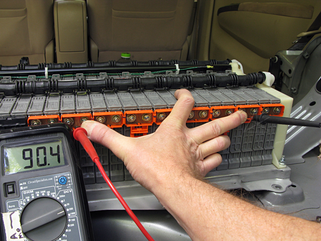
I pick one of the worst looking ones and carefully remove the nut. Some
major apprehension here is the possibility of shearing one of the module studs
off, which would leave me well and truly scrod, so I'm really tentative about
applying torque. It's on there pretty tight, but eventually turns.
While an interesting gradient of oxidation pattern has developed across the exposed faces of the straps, the backside of the nut and the copper right under it is clean and fresh. |
|
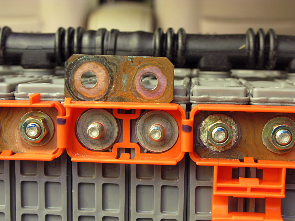
The other nut also comes off and the strap is popped out of the holder and
turned over. Here's the important part -- the connection right at the
flat base of the module stud and the strap is clean, showing a good solid
connection that's not going to complain about passing 100 amps on occasion.
None of this stuff seems to harbor the mystery odor, either. So, no idea what the white fluff is -- some minor side-effect from dissimilar metals in contact, probably, but nothing to worry about at the moment. It's interesting how the oxidation/discoloration has crept in a little under the parts that the nut isn't directly clamping down, and something to keep in mind for a possible end-to-end cleanup much farther down the road. |
|
I did indeed get back in here for inspection, *another* six years on after
this adventure, and not only did said cleanup but also changed over to a
completely different set of interconnect straps. Read about it here. |
|
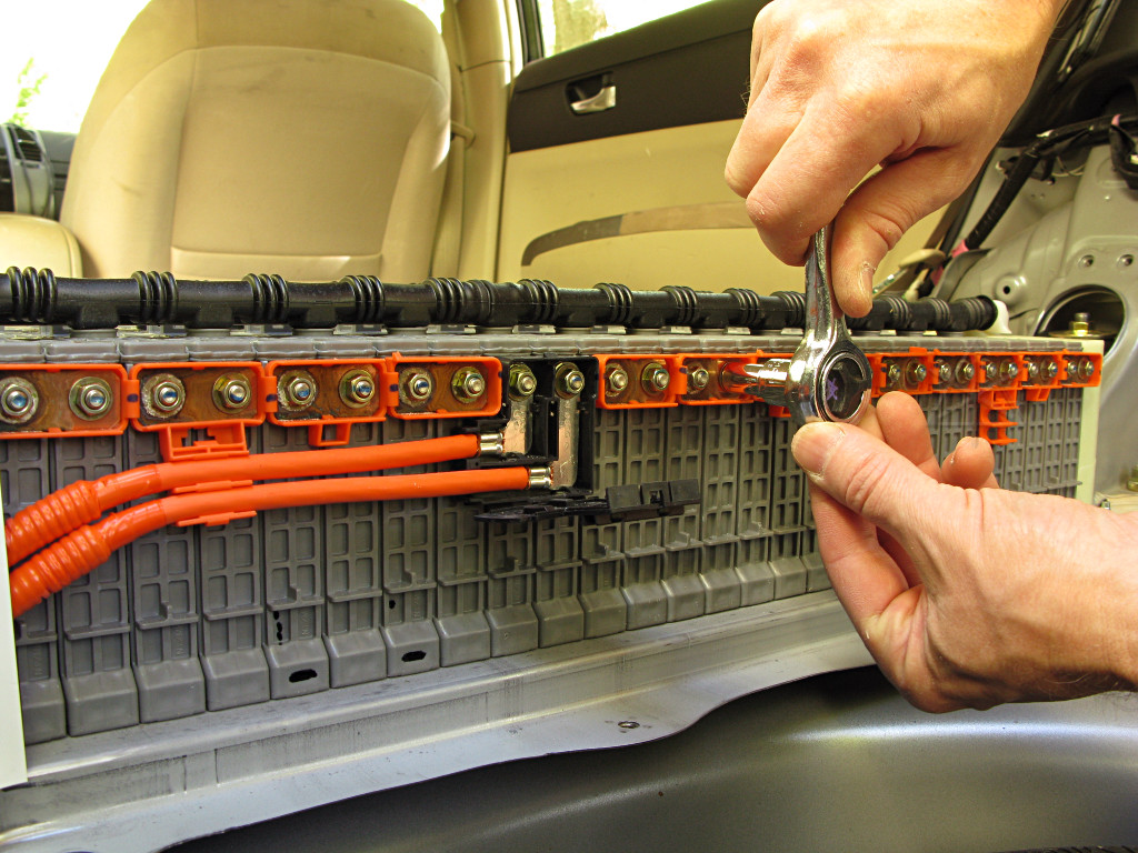
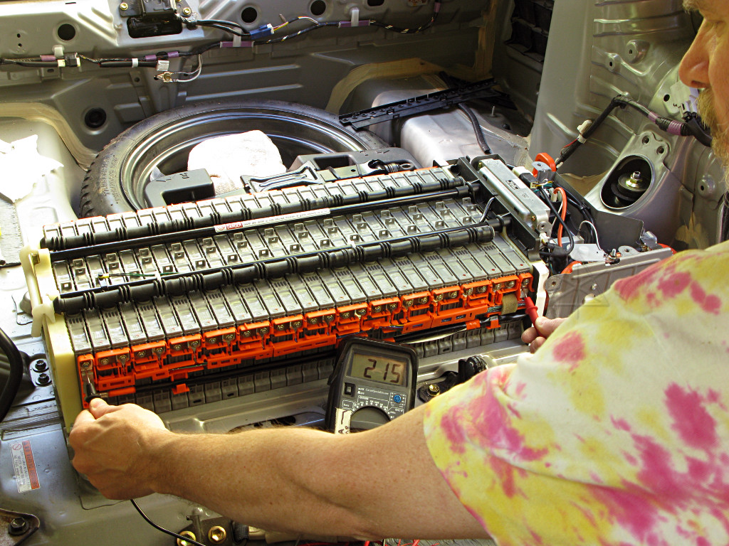
So I infer that since they all look about the same externally that they're likely in all about the same internal condition, and that taking any more of them apart is not needed. Instead, just because copper and other soft metals *do* sag a little under long-term stress, I decided to give each connection an affectionate little tightening tweak just in case any of them were slightly looser than others. Some nuts move a little, some don't, but I figure that now I've got all of them more uniformly torqued in. |
| Now, the safety-astute might view this procedure with horror -- a metal wrench handle, bare hand, and right onto a battery connection. Without my 1000-volt gloves on. Why am I not an instant crispy critter, accompanied by that cartoon "fzzZZZvvvZZZT" sound? |

|
|
Okay, let's stop and think rationally about this for a moment. 220 volts,
the nominal real-life running voltage of the pack, is on par with ordinary
household wiring which electricians work on every day without gloves. They
know how to not be stupid about it, know what's safe to touch and what
isn't and when, and how to make things safe for themselves as needed. One
difference is that where household wiring is AC and contains zero-crossings,
this is DC and at least until relatively recently, was popularly considered
to have more of a tendency to lock up muscles at relatively modest levels
of current through the body. [This is still being researched and worked
into safety standards; see
this paper
and some of the ongoing work at
EFCOG
for more. It's kind of hard to engage human volunteers to help nail
these things down...]
But the key concept for any hazard is that one needs to complete a circuit. With the car powered off and the battery-box relays open, there is no connection between the battery and the outside world and least of all the car body since the whole hybrid HV system runs isolated anyway. The only available high voltage along the battery pack would come from grabbing terminals at *two* places, at a fairly wide separation. Each module pair presents about 16V between the straps where the serpentine turns around, so the voltage hazard would step up by about 16V per hop as the second point of contact moves down the pack. Obviously one doesn't want to short-circuit any of this as the high current capability could rapidly heat anything metal and cause arc flash and fires, but without substantial separation the current likely to pass through typical skin resistance is quite low. But skin resistance can vary quite a bit depending on moisture and contact area. Some people would have issues with a 24V doorbell transformer. My fingertips tend to be fairly dry, and I routinely test for 120V household voltage by poking across the terminals and feeling a little buzz. Unless I'm grounded in some other way, like working barefoot on a damp concrete floor [been there done that], it's safe enough as long as the touch is with the correct part of the fingers and the available voltage is known. It's a little more entertaining if I'm sweating, and I hesitate to test 240V this way as it's a bit too much tingle unless my fingers are *very* dry at the time, but I have on occasion. So how much of a Prius battery is safe for the "human voltmeter" test? Well, I can cheat a little on this determination: I have a variable DC bench supply that goes to about 500 volts but fairly low current output and using that, I have my "two-finger the alligator clips" test up around 150V before approaching anything like a pain/discomfort level. That's at about one milliamp, where five or so is considered dangerous and for the most part only if taking a path across the heart. Now let's go back outside and play. |
|
At the maximum extension one hand can reach, I can bridge 90 volts worth
of the pack. And I have to press *hard* to feel anything at all. Those
who have worked on analog phone lines may know what 90 volts feels like if
someone happens to dial in just when the wires are being fiddled with, as
that's about what the ringing signal is. I don't think that ever killed
anyone, just gave them a little surprise and the option to clip in and
answer the call.
Regardless, in our overly litigous society I'm required to say... do not try this at home. Trained professional, controlled demo, closed track, defibrillator on standby, etc. |
|
The voltage across the whole pack, of course, is not something I'm going
to go ahead and grab with two hands. Nor am I going to go finger-bridge
the inboard side of the main relays. But I can certainly see where the
ends are and measure it. The voltage is not going to leap out and zap me
for looking at it funny, as some of the hybrid-battery FUD would almost
have us [and numerous misguided auto techs and first-responders] believe,
even still after all these years of hybrids being on the road.
On this side we also have all the block-pair monitoring leads that tap the string and bring 14 voltage measurements into the battery ECU through isolated sensing circuitry. For those inclined to ask, these taps are *not* used for any kind of active balancing -- they're just sense leads. |
|
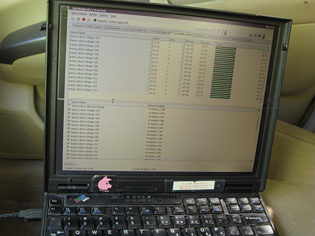
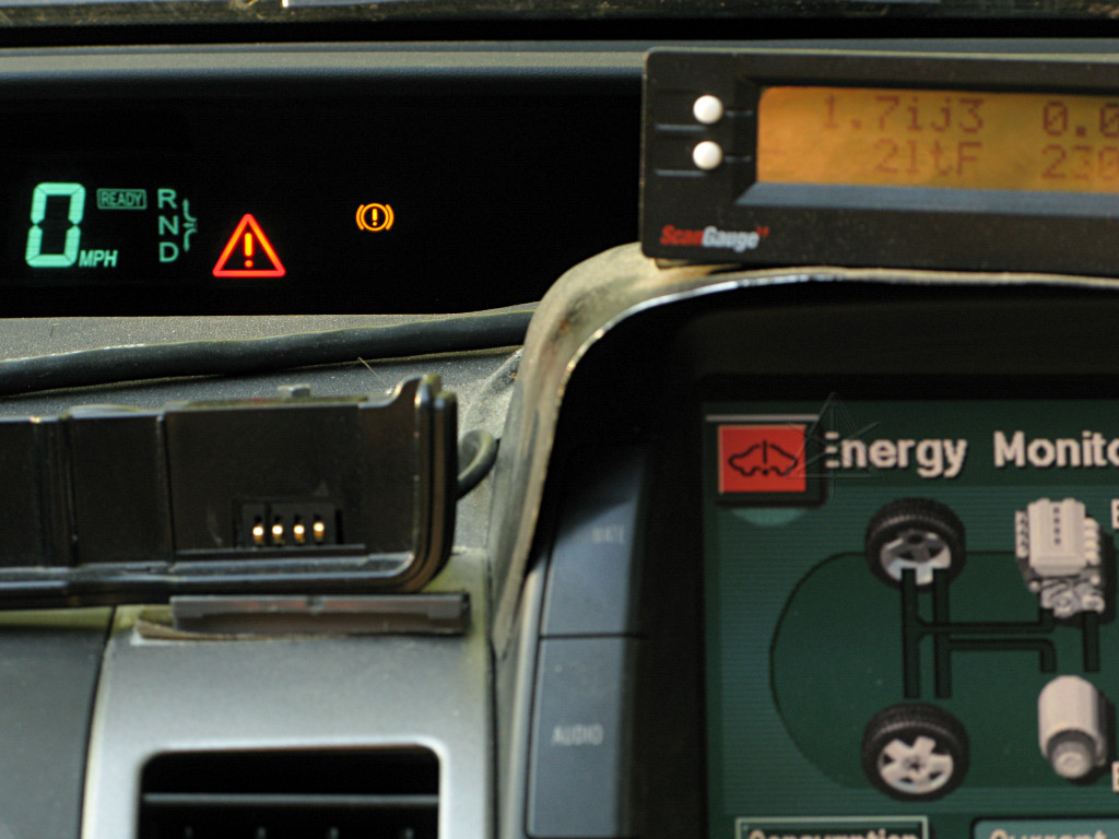
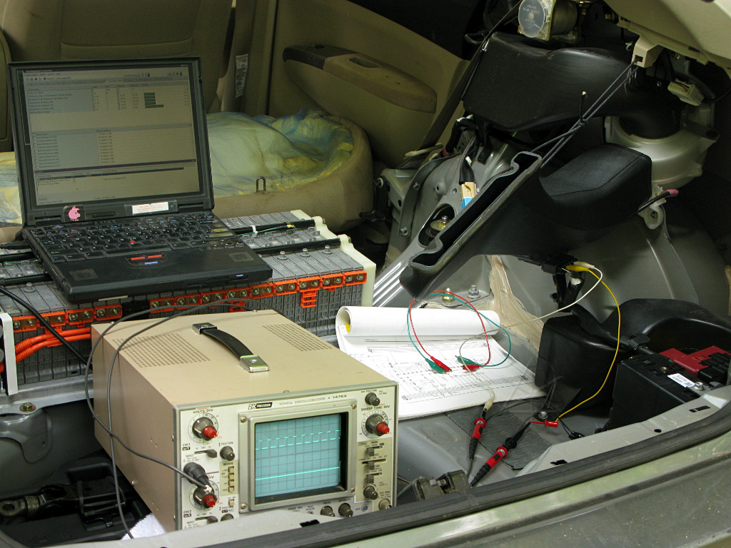
These block voltages can be queried and displayed with a suitable scantool, in this case my slightly out of date version of AutoEnginuity with the Toyota manufacturer-specific enhanced diagnostics enabled and conversing directly with the battery ECU. Watching these during various charge/discharge load tests can help isolate a failing module if any exist -- it would be one of the pair whose block voltage swings more than the others on current-flow changes. Of course the battery ECU itself looks for such anomalies and sends up "battery block N grows weak" error codes if things get too out of whack. Which, I'll add, is an *extraordinarily* rare occurrence in a second-generation Prius to date. |
|
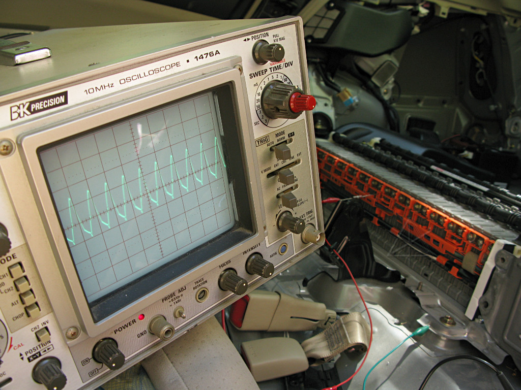
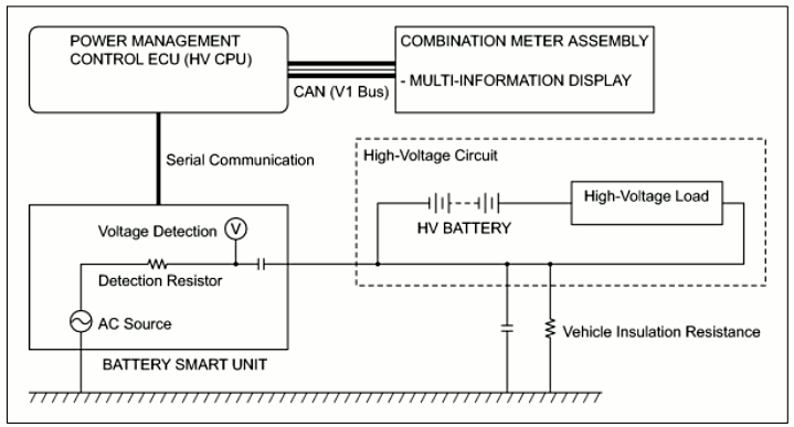
Another appropriate thing to look at is the ground-fault detection. With the car powered up, we see a roughly 5 KHz waveform superimposed on the battery voltage, which is applied through a sense resistor to detect if part of the oscillator output is leaking out to somewhere else from either side of the system or post-inverter motor connections. Interestingly, I can *hear* this high tone very subtly from around the battery area when the car's in anything other than Neutral. But "battery voltage" is sort of a squishy concept here -- relative to the car body ground, the middle of the pack happens to measure close to 0 volts, and the ends measure around +100 or -100 when first metered. But then just the tiny trickle of current through the *meter* itself causes that measured voltage to drift back toward ground, until the meter is taken off after which it recovers [and the other end reads commensurately farther displaced away from ground in the meantime]. That truly shows how the entire system relative to the rest of the car pretty much floats, including battery, feed wires, inverter power modules, and both motors. |
| As does this, albeit taken from the third-gen Prius documentation where they actually explain it a little better than in the '04 manual. The "high voltage load" is everything else in the car with the scary orange wires. |
|
|
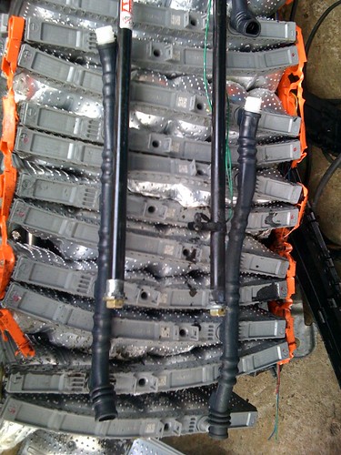
By now I have a suspicion that the black rubber tubes fit over the vent valves on the battery modules are the source of the smell. They feel sticky, as though the rubber has been chemically degrading, and smell rather strongly themselves. I pull them off in the course of disassembly, and then drive the car around for a few days with the pack still naked to the world to see if I can detect any of that same smell coming from the battery itself. |
|
Since the hoses were connected over the vent valve barbs, it takes some time
for the remaining smell around them to dissipate. After a few normal
drive cycles it vanishes entirely and I can detect *no* odor whatsoever
coming from the vents themselves or anywhere else around the pack. It's gone.
And that's after some healthy abuse -- high regen currents, EVing as far as
the limits will let me, force-charging, etc. In that process I'm also
testing for pack and interconnect heating, to try and make sure there aren't
any potential bad areas or higher-resistance cells. With the thing completely
open to the air like this the fan cannot cool it, but convection and overall
air circulation through the car certainly can and the weather isn't
particularly warm yet. It's easy to pull over somewhere and feel across
all the modules for any unusually warm areas that could point up a weak cell
or link, but I happily cannot find any. In this configuration, sunlight
through the windows causes more pack warming than any electrical scenario
I can put it through.
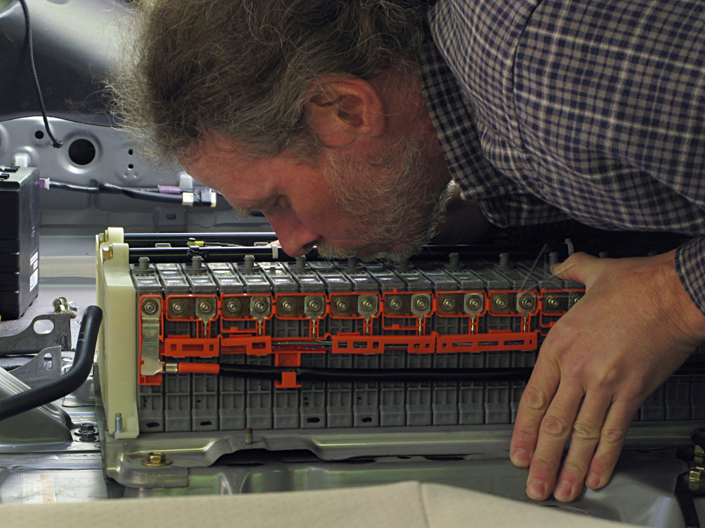
And where else do you get pictures of a hybrid enthusiast snogging his own battery? |
|
It's not clear that these tubes *ever* pass any gas coming from
the batteries. In the experience of everyone I know who has overcharged
these modules, the vents never actually vent. Instead, pressure builds
up inside the cases and they bulge out at the sides, puffing like chipmunk
cheeks if things get bad enough, and can force their way right out of a fairly
strong battery enclosure from the combined pressure and bend themselves
into useless crap in the process. You would think that the vents would let
go to relieve the overcharge pressure long before the point of destruction,
but I don't think *anyone* has ever observed them actually doing so.
As tempting as it is to leave the silly tubes off entirely, I put them back in so they can continue stinking up the seat vent. At least now I know what the deal is.
[picture credit: aminorjourney @ priuschat's PHEV thread -- a fascinating tale!] |
|
During reassembly, I've decided to add a main battery tap. Post-relay,
where it belongs -- none of this BS about sneaking around behind the current
sensor. If I ever build some kind of PHEV rig to inject extra juice into
the system, the car is bloody well going to know about it and keep track
of its own real SOC. I've decided to use a typical L5-20 plug and run
through the two larger size blades which are normally neutral and ground.
I don't expect to ever want to push more than 20A into or out of the system;
any proposed current injection via a PHEV lashup would only be a gentle
"SOC helper" like the
Enginer system.
More likely would be a heftier inverter or UPS whose native battery voltage
is around 220V in the first place. That would yield about 4 kW, enough to
power most things around a home or many types of remote event.
A short 12/3 cable runs out one of the few non-sharp-edged case holes and the twistlock receptacle tucks neatly into the corner by the suspension tower and safety plug for whenever I decide to actually do something with it. While the green wire of the cable runs to the case at one end, it doesn't emerge into the receptacle at all for now. |
|
I think that in slightly different ways, both the Hymotion and Enginer people
have substantially proven that using a proper regulator to send controlled
currents into the Prius HV system while letting the car's current sensor
see it is the correct way to go and doesn't cause the error conditions that
the frankly bumbling contactor-based PHEV systems do if they connect at the
same points. While the early experimenters assumed that it was due to
battery/motor current mismatches double-checked by various ECUs, it is fairly
clear by now that instead it's all because of uncontrolled cross-currents
between packs and high spikes at the moment of relay connection. Regulated
systems don't have this problem. Read between the lines in the early
CalCars experiments
and it becomes pretty obvious that they, and all who have followed in their
footsteps, were going at it in a really ham-handed manner doomed to fail.
Especially with mixed battery chemistries involved. *Shiver*.
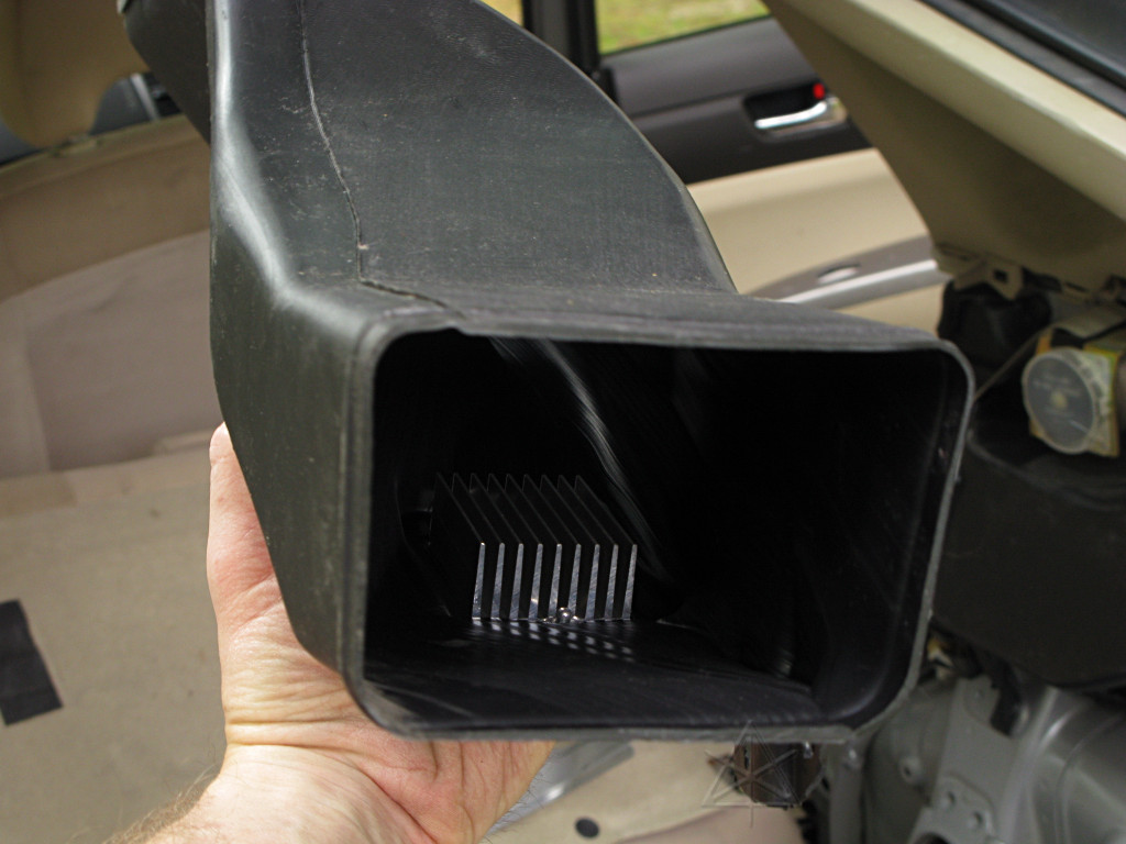
Fan investigation One concept kicked around among the tech community has been a battery warmer to bring the pack closer to its optimum performance temperature on cold days. When it's too cold you can't get into EV mode, your regen is limited to 40 or 50 amps, and in general the pack just isn't happy until it warms up a little via a combination of self-heating and warmer cabin air requested by the driver. At some point I noodled the idea of using one of those flexible rubber heating elements under the thing, but with the box apart I now see that the lower inch and a half worth of height is all air duct and heating under that probably wouldn't do much good. And trying to directly heat under the modules would block all the airflow! So if any sort of pack heater were to be done, the right place might be a PTC heater in the duct airflow and a way to run the fan to push the warm air in. Except that in this setup, airflow through the pack is *downward* for some inexplicable anti-convection reason and would probably work even less well than expected. Still, it's another potential reason to want to run the battery fan, so let's have a closer look at all that stuff. While I don't know the exact wiring changes done, I know that one or two of the PHEV kits out there include parts to rewire some of the related stuff and run the fan motor full speed on demand. I think it's usually a klunky setup with relays to just swap the fan leads over to fixed power, but having noodled out the variable-speed fan controller for the climate blower I assume the same concept should map to an elegant solution for this one. |
|
For the most part we're going after the speed control which is mounted, for some bizarre reason, in the *output* side of the ductwork. It's also sealed and pop-riveted onto the plastic, so we're not going to see the innards of this one. |
|
Similarly to the A/C setup, the controller is cooled by the airflow from the fan that it controls, but you'd think this would be better located right after the fan itself rather than after the entire battery, which is presumed to be overly warm in the first place when the fan needs to run. Thus the controller heatsink isn't seeing the coolest air in the path. |
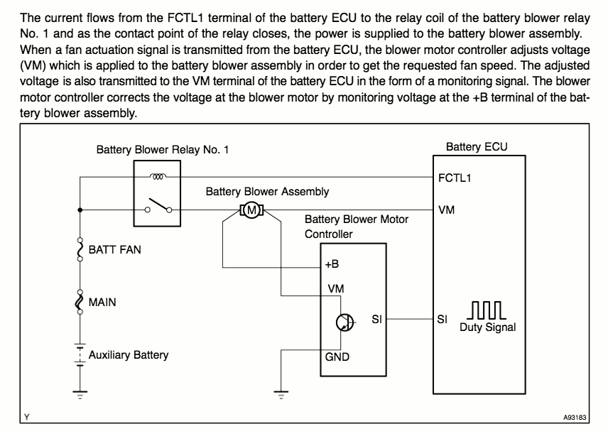
Here's how the control setup works: the blower system is commanded on by enabling FCTL1 to bring power to the fan and controller, and then the battery ECU provides negative-going PWM to regulate the speed. There's a problem, though: the battery ECU also *checks* how fast the fan is running by monitoring the switched-lead voltage at VM. |
|
And they're not just saying that, either -- it really does check, and fooling with the SI lead to try and run the fan faster is very likely to produce an error condition. Interestingly, the additional idiot-light that comes on is for the *brake* system, probably reducing available regen at the same time to protect a fan-impaired battery from high heat-building currents [I haven't actually checked this]. The car doesn't fall out of READY or anything and will power up and down normally, but once set, this error seems very reluctant to clear until all 12V power is *removed* from the battery ECU. The normal 4 reboots of the car doesn't always do it. |
|
The appropriate scantool can command one of six fan speeds. Here we can see
the PWM from speed 5 or thereabouts. The measured voltage at the down side
of the fan motor is quite steady. The battery ECU seems to slowly ramp up
toward the commanded level through all of the intervening speeds by itself,
slowly enough that the scantool is actually able to catch all of the queried
level changes in between -- and bi-directional communication with the battery
ECU is usually dog-slow, so that's quite some observed lag. I believe the
battery ECU is doing this internally, as opposed to the *scantool* walking
through each level on its own, but I can't confirm that.
In the error state, the fan seems to just run at a continuous speed 1 which is fairly low but keeps air moving through. |
| Unfortunately, this voltage-checking at the ECU is makes it much more difficult to run the fan at a *different* speed than the ECU is holding at any given time, without a fairly complex fakeout to keep it happy and relays inserted into leads to swap from one functionality to the other and now we're almost back to the same PHEV add-on. Sure, one could hook up a scantool and command test level 6 but that's overly clumsy and needs the laptop set up. I was hoping to to just be able to ground a couple of leads through diodes and have the right thing [i.e. big blast of air] happen, like grounding one ECU pin makes the front radiator fans go full-on without any complaints. Perhaps the correct diagnostic command could be blindly sent over CAN by the Scangauge or something, but for now this little project is put aside as "not trivial" and I'll either just live with a warm butt on the roadtrip overnights or plan ahead and use more A/C toward the end of the day's run and hope that enough cooled air finds its way through the battery ductwork. That's how battery ventilation is supposed to work -- using the same air that keeps the human comfy to keep the battery comfy in a similar temp range. Besides, it's obvious that the seat cushions and other stuff can hold a lot of heat as well, so it's unclear how much advantage venting just the battery would really bring. | |
|
Finally it's time to reassemble everything, taking the opportunity to get
a smidge of anti-seize onto all the bolt threads.
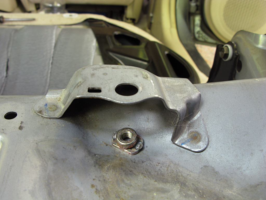
This captive nut for the luggage D-ring lost its spot-welds to the battery box suspension-tower brace. Maybe this cracked off from using the ring to strap in the big UPS. Nothing a little tape can't fix; it only has to hold long enough to get the panel on and the bolt threaded in. |
|
A minor side trip is taken on the way, to answer a long-standing question.
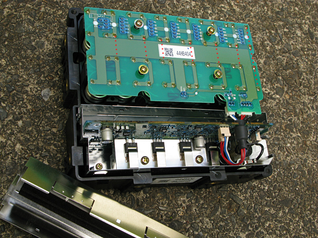
There's been a little debate over whether the backup power supply for the braking system contains supercaps, regular caps at some other voltage than 12, or whatever. Time to resolve it. In addition to a largish rack of electrolytic capacitors the box contains a well-shielded and fairly complex-looking power supply board, so *my* initial, untested assumption was that it uses ordinary 'lytics at a higher voltage than 12 just to be able to store more energy per, and then steps it back down to feed the brake system. There's a fairly complex protocol between the car and the box to enable and monitor this supply, so clearly there's something special about it and it's not just the "big-ass cap" you hang off your aftermarket stereo for better bass. |
| The caps are wired in an odd series-parallel matrix, 7 x 4. I've added orange dots to this picture to show the interconnects on the other side of the board, and there are little groups of ladder-balancing resistors up the chain to equalize voltages across the string. This *is* starting to look like an ultracap array. | |
|
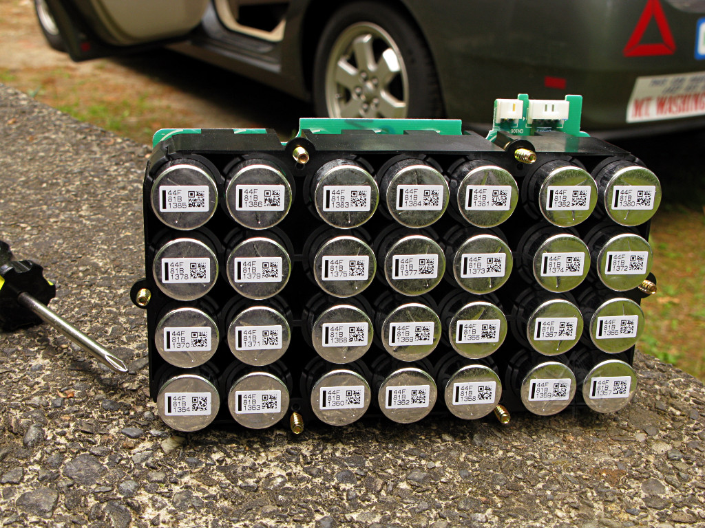
Well, whoever said it's supercaps was right. The "44F" on the label is not
a part number! No indication as to rated voltage, but when the box is
powered up each one of these cans reaches a maximum of 1.84 V across it and
the series string adds up to 12.9. The rack charges fairly slowly, likely
current-limited by the surrounding circuitry, and discharges *very* slowly
after losing supply power from the car -- two minutes later, it's still at
10 V and slowly sinking. So it's sort of like a battery but only has to
last for a couple of stops' worth of running the brake ECU and solenoids,
the electrical equivalent of the vacuum booster. The complex power supply
is most likely a boost circuit to keep the output voltage at 12 for the ECU
as long as possible while the caps discharge to much lower than that, as
ultracap discharge voltage is linear down to 0 and looks nothing like the
flatter curve of a battery.
Another clever but possibly somewhat overengineered solution from Toyota. They've done away with this in the third-generation car, perhaps deciding that hydraulic backup using the pressure reserve and valve-based force distribution is a better way to go. |