Each picture is a link to its larger version, so you can select each one
for much more detail.  Use your "back" button to navigate.
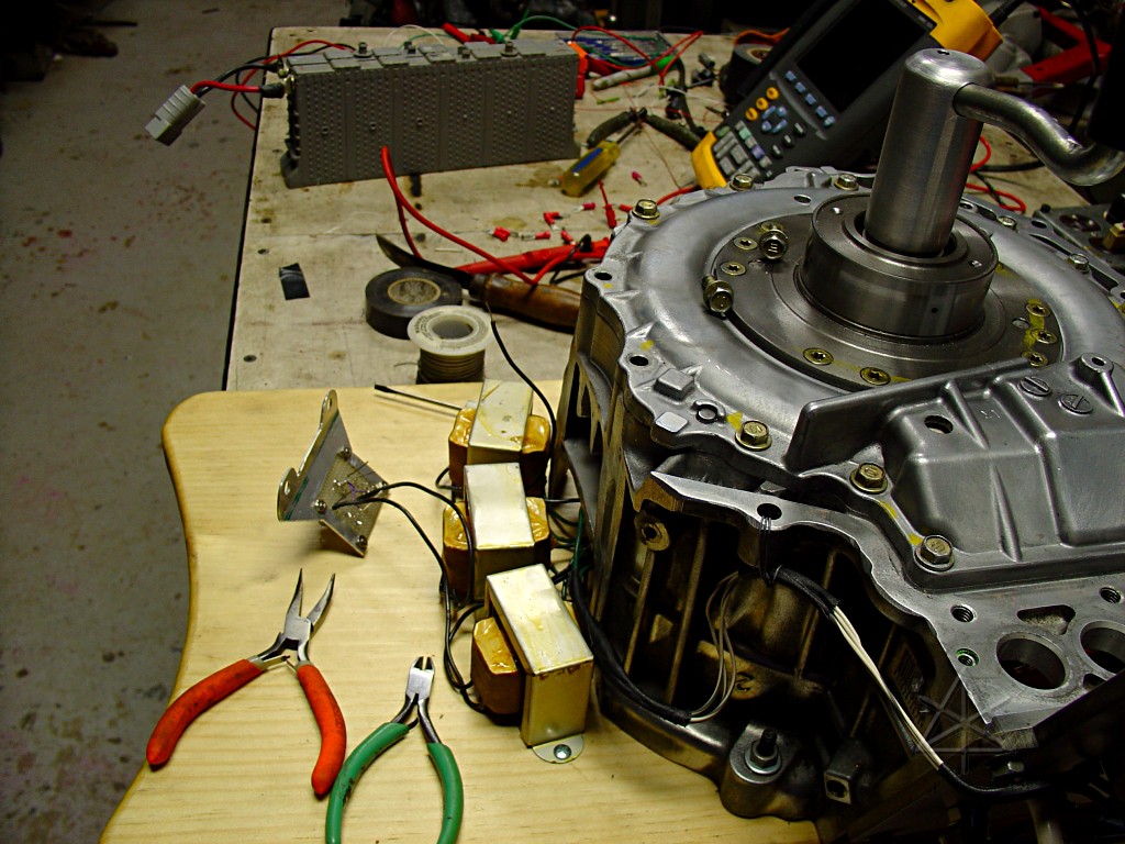
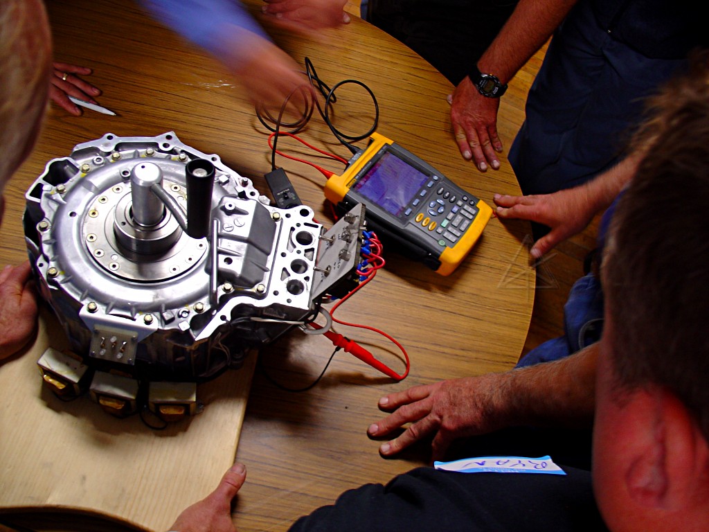
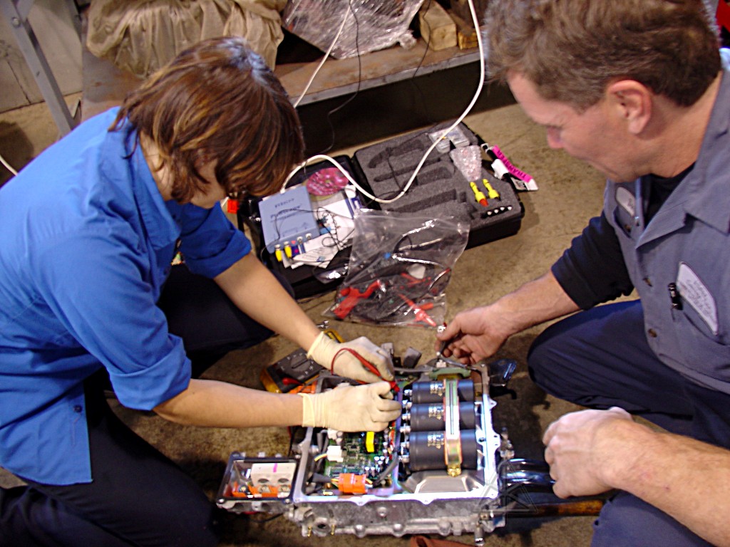
I went to Mike's house the day before to help him finish up some of the
demo pieces ... he did the vast majority of the work on these, but we
came up with a few bits that I could do while he was working on the last
major piece.  Here, I was in the middle of adding a red/green display
of the three phases to the "cranker" -- a Prius MG1 with a handle fitted,
so a human can experience just a tiny taste of how much work regenerative
braking involves.

All of this stuff came out of a Classic Prius transaxle, that Mike bandsawed
apart in various ways to extract the good bits and remount them more
portably and visibly than in the original transmission.

Yup, that's a pair of Prius NiMH modules in the background hooked together
as a convenient handheld 15V supply with a *lot* of current capability.
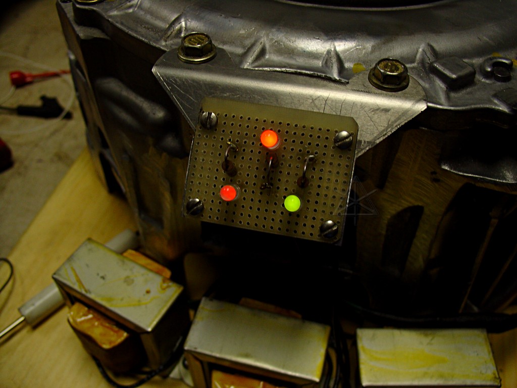
Problem was that MG1 actually produces much more *current* than voltage,
so to see the pattern at low speed, some kind of booster was needed.  Mike
scared up a trio of 24-volt transformers which I hooked up backwards to
boost the voltage a little.  It was just enough to light the LEDs and still
go slowly enough to see the four electrical revolutions per physical one.
[Ask me just how tempting it is to do up an animated .GIF to show this...]

Without the boosters, MG1 only produces 18V or so with a good fast whip-around
on the crank.  With them, we're up around 60V peak open-circuit.  But if you
*short* all the MG1 outputs together and lay into it really hard, you can
get over 50 amps through any one lead.  That's quite a bit from a relatively
small generator.  Strong magnets, large-gauge coils...
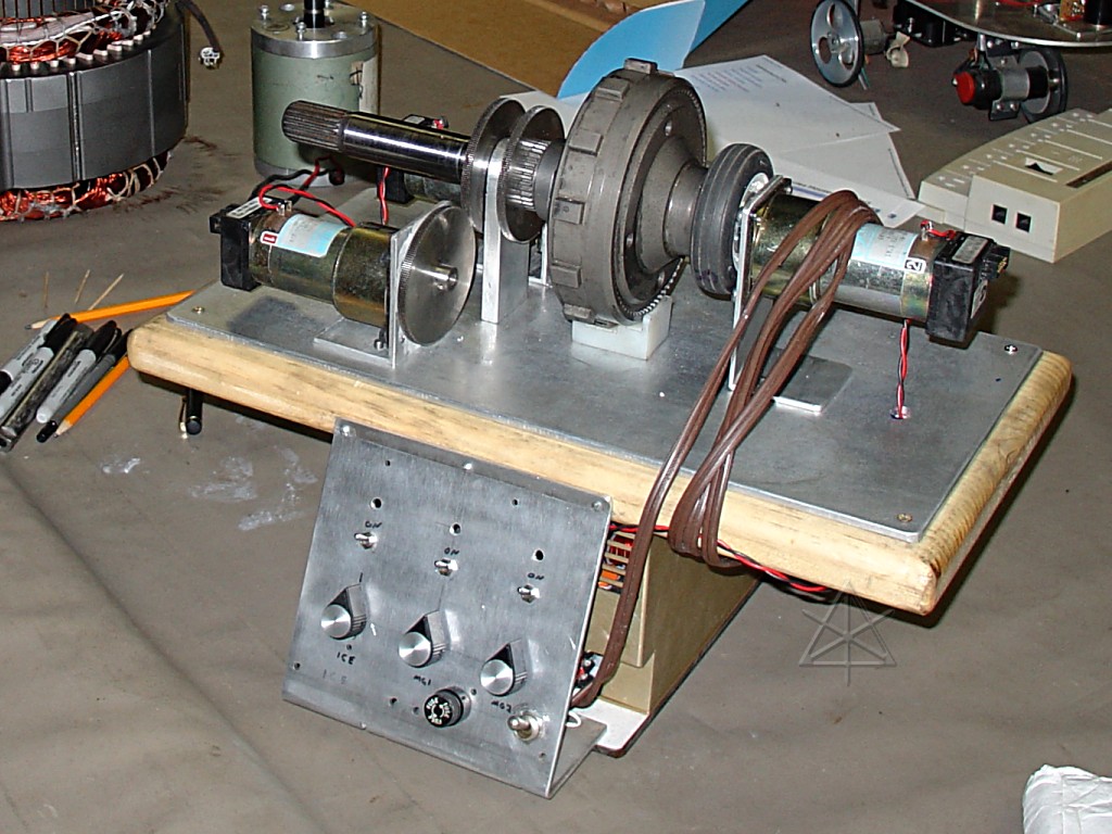
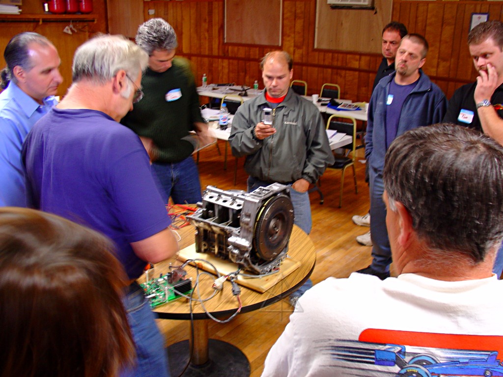
Meanwhile, Mike was finishing up this -- the PSD planetary drivetrain,
remounted on a plate with drive motors and bidirectional servo control
so you can sit there and play with relative speeds of all the parts.  A
very nice little hack, and also mounted on one of his signature chamfered
and varnished boards.  We probably didn't spend enough time running it,
either, but between this and my "baby PSD" bicycle planetary and the
silly nomograph-stick, I think greater understanding was had by all.

But what's that big thing in the upper left corner?
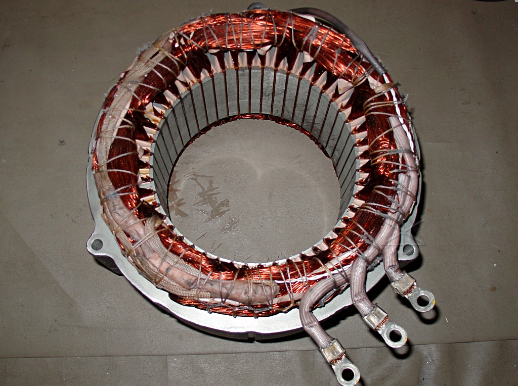
It's the big heavy stator windings from MG2.  We decided *not* to bring
this extra 40+ pounds...

But we did bring the MG2 rotor, just to show how strongly magnetic it is.
That nut is *very* firmly stuck between two poles.  At the previous training,
at least one guy couldn't get into his hotel room the night after we were
playing with all these rotor components.

So with this transaxle all split apart we didn't have a complete one to
disassemble on-site, or at least not conveniently [see below].  But we got
some decent pictures of this same unit pre-dissection from UYV2, located at
the obvious URL if you look at where this page lives.

Most of the heavy stuff went into *my* car, since Mike's Insight isn't
exactly the best freight-hauler.
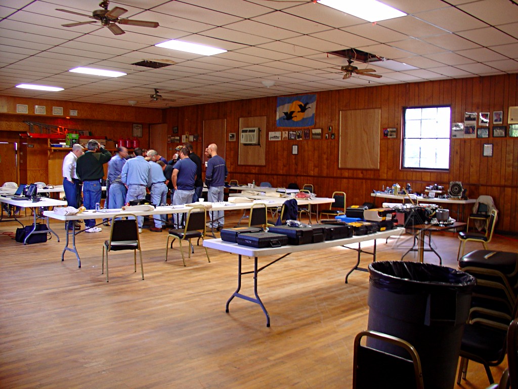
Day 1: classroom, in a rather nice American Legion hall.  Lecture alternated
with everyone clustering around for various demos.
Generic waveforms from spinning the generator...
Running the Insight IMA from a little 5-amp driver from Microchip.  It could
barely get the flywheel spinning against the relatively high friction from
the crank journals even though we kept them clean and oiled, but it was enough
to prove the point about how the Hall-effect sensors tell the controller to
switch windings.
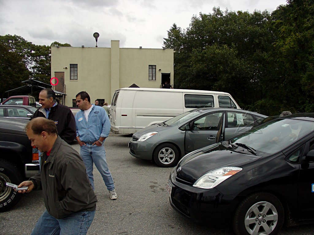
The back of the hall.  In between class and demos, we all trooped outside
to play with the cars themselves.  The red circle indicates where the yellow
jacket nest was in the wall behind the doorframe; we decided to use the
*other* door...
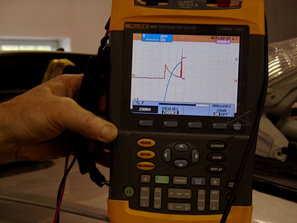
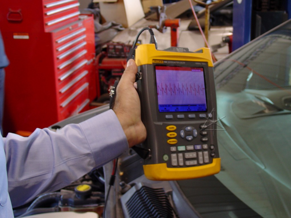
Next day, in the shop, tearing apart cars and pulling any and all signal
characteristics out of them.  Here we've got a beautiful voltage and current
trace as the HV battery connects to the inverter, first through the precharge
resistor and then the main contactors.  At one point I had my head down
right over the battery box when someone powered up a Prius, and I could
physically locate the three relay clicks in "stereo" space.

Just *listening* to the noises these cars make is very instructive.
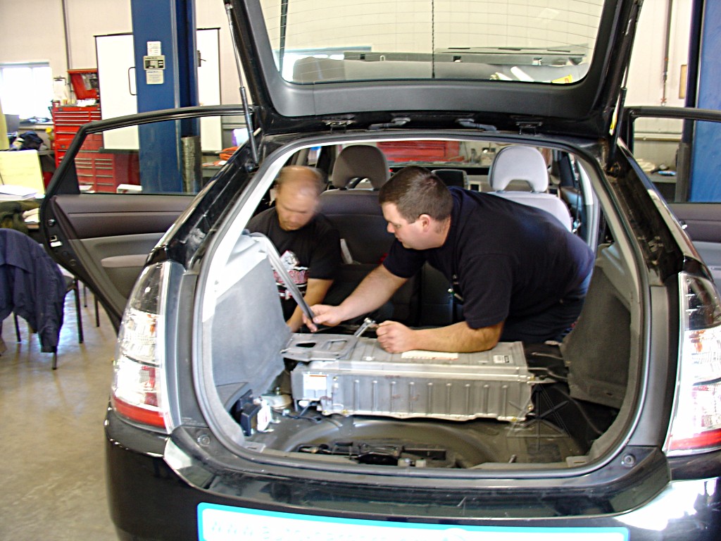
Yep, another lousy pic -- the risks of natural-light shooting.  Whatever.

The folks really wanted to pull battery packs and get used to the idea of
handling them safely.  It was gratifying to hear several times over the
weekend statements like "gee, now these things aren't so mysterious and
scary".  This is good news for how they can help salvage yards and first
responders, too...
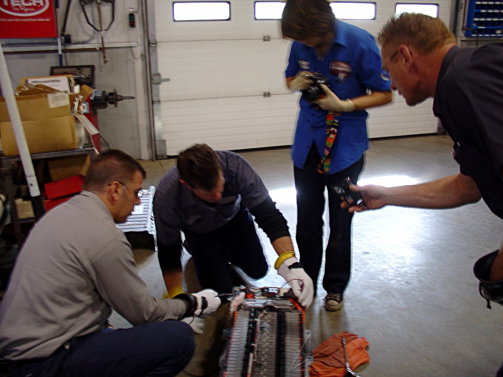
Walking down the pack modules, noting voltage increase as we test farther
along the string.  8 modules gives about 60 volts, where things start getting
a little dangerous.  Even with the service plug out, there's still 150 VDC
or more available here which is not to be sneezed at...
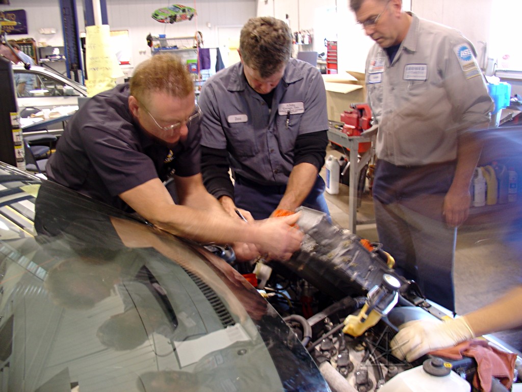
Next thing was to yank the inverter, to get used to the dance of draining
its coolant loop and unhooking all the 3-phase and battery wires.  There
are actually several service things you can do by simply shifting the
inverter aside without draining it, but getting it out of there completely
really opens everything up.
Various ohmmeter tests on its innards... [This is a Classic, obviously]
Current-ramping the inverter coolant pump.  Everyone agrees these things
feel sort of cheezy and subject to failure, and they run *all* the time
the car's powered on.  but I myself haven't actually read of any failures/
replacements yet.  Maybe I should search the forums again...
Current traces from the three phases driving the electric A/C compressor.
I fetched out my "terminals of ECU" bible and hooked up my listener-widget
to hear the NEO line, aka the nice buffered crank-sensor output sent between
the engine ECM and the hybrid ECU.  People were amused to hear that this rig
was my first tach, when I drove around for two days just listening to this
little box whining up and down.  Useful tool -- *hearing* a signal often
tells you a lot about it that even a scope might miss.  It's just a little
piezo speaker in series with a 47K resistor or so.
Meanwhile, over in Honda-land they were running the Civic IMA as a
straight-up genset and lighting up a kilowatt of work-lights.  Rev 'er up!
Some quick math over someone's AC frequency vs. engine RPM measurements
ballparks this IMA as 18 pole [3 * 6], just like in the Insight.  As
contrasted with all the 12 pole Prius motors, of course.
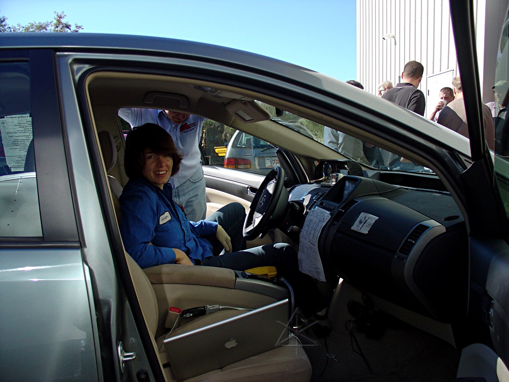
Then, it was time to pull the long litany of history DTCs that *my* car has
accumulated in the year and a half I've been messing with it.  I can explain
every one of them, too.

[She's a real instrumentation/diagnostic fiend, and spent quite a while
in deep conversation with my Prius over the course of the weekend...]
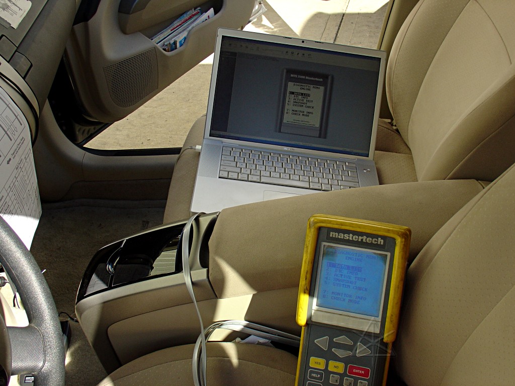
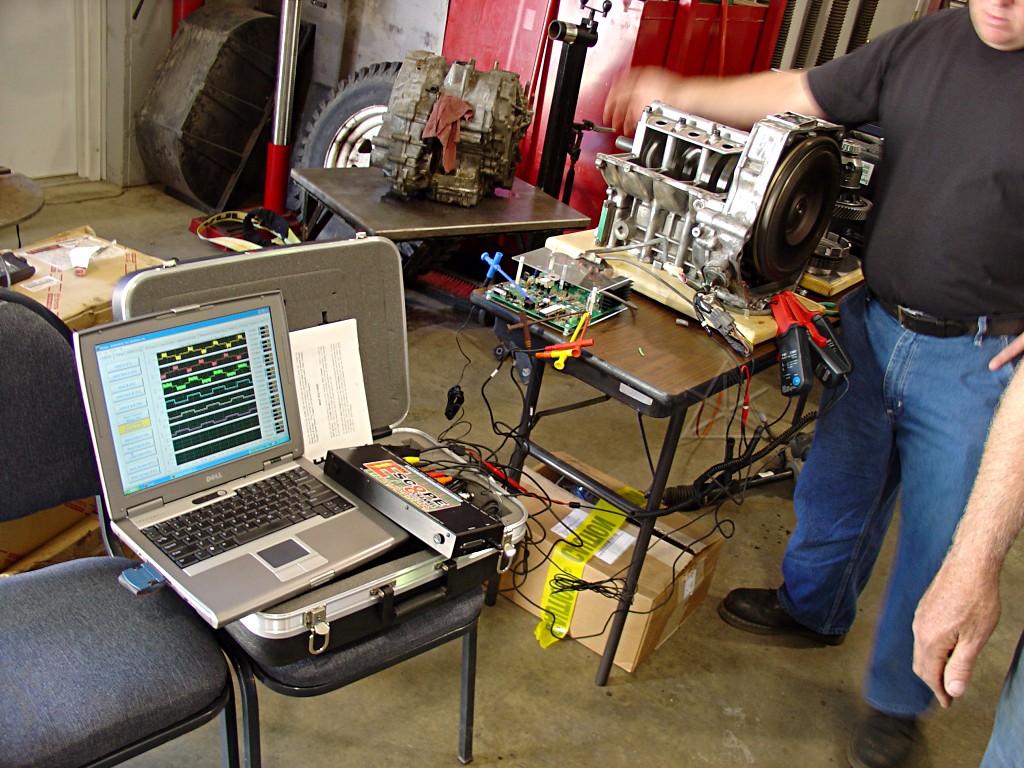
Hmm, which has more computing power here, the car or the tech?  We managed
to get the Vetronix to send a screen-dump to the laptop, but the control
stuff in the other direction kept refusing to work.
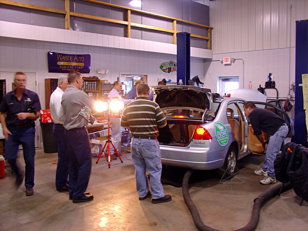
Later, it was time for a new crew to rip-n-tear into Craig's car.
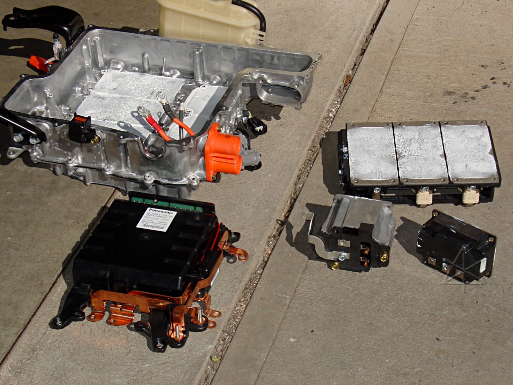
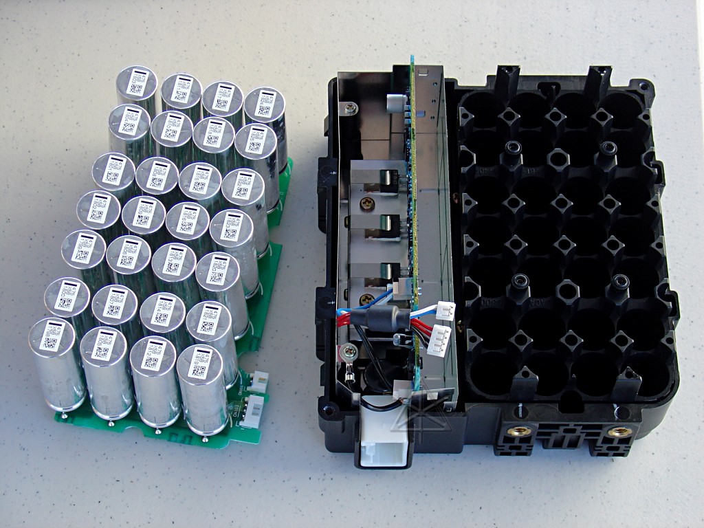
They were keeping themselves quite busy, so I dug out the spare '04 inverter
and set up a little photo-shoot outside.  Here are the major parts pulled
out of the top -- driver board and IPM, the boost coil and IPM, and the
capacitor module.  The IGBT modules sit right against the cold-plate with
a plentitude of that white heat-sink grease, ick.

We measured that wacky bleed-resistor assembly on the side of the cap block
at 63.9K, done in a 5 x 12 series-parallel array of 27K chip resistors.
Weird way to do it, but maybe that yields lots of radiative surface area.
When a Prius is powered off, though, inverter voltage drops *much* faster
than this bleeder could possibly bring it down.
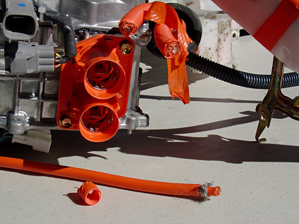
This is what the battery feeder cables look like -- they're coaxial.  The
shields run all the way along around the actual battery and motor conductors,
and should be isolated and then megger-tested to ground in any collision-
repair situation as well as the battery leads themselves.  If the wire's
damaged chances are good that the center and shield leads will short together
and throw a HV ground-leak code anyways.  That's probably what they're for,
in fact.
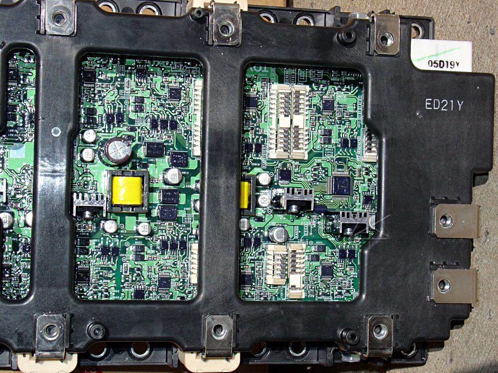
The drive board and main motor connections.  The little white five-pin
connections go down to the IGBT gates, and the outputs come back up through
the current-sensor donuts on two out of three legs.  The two large leads at
the right are the boosted 500V rails in, feeding both racks for MG1 and MG2.

On the bottom side of the inverter, we've got this: the 12V DC/DC converter
and the A/C compressor drive.  Various power components also sit against
the cold-plate here, including the transformers [which, we note, use
rectangular cross-section wire for higher current density].  This board
looks similar to what's found in a commercial UPS -- funny that, huh?
Here is a huge, detailed view of it [1.3 Mb].

The 30A fuse feeds the 200V supply to everything here.  If 12V charging
and the A/C fail together, that might be where to look!  But given that
it's soldered in, they apparently don't ever expect it to blow.
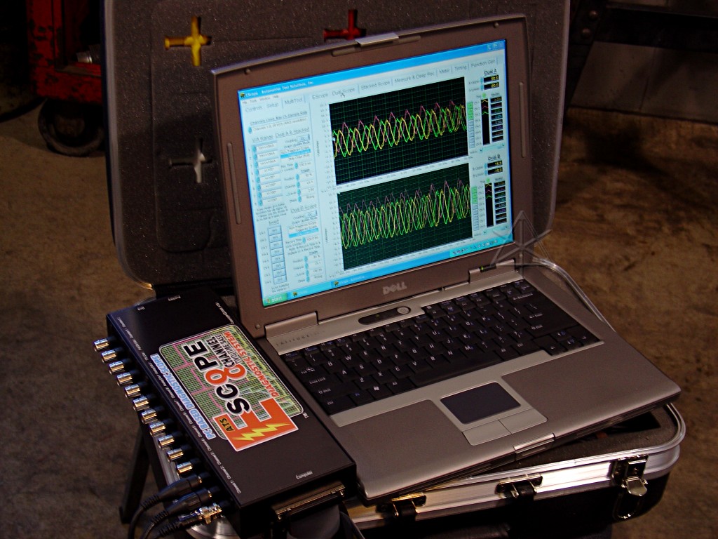
The IMA demo running again, but this time with six channels of monitoring.
The E-scope can do eight channels, and even more if the boxes are cascaded.
Pretty slick.  And it's even relatively fast, in painful contrast to the
Fluke scopemeters.  One phase drive of the IMA [in green] looks different;
I'm still not entirely convinced we wired the Hall effect sensor inputs
right or the controller isn't producing something odd.

Inside the capacitor backup power supply for the brake-by-wire system.  This
is theoretically just enough power storage to get you safely to the side of
the road if the whole 12V system dies, and if that's not enough there's still
the physical hydraulic backup too.
The caps, once pulled out of their funny [and very tight!] plastic holder.
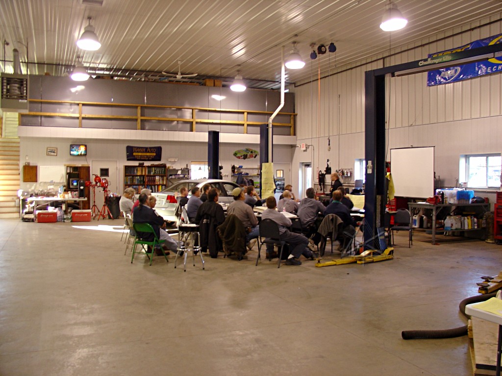
The makeshift classroom set up in a dead bay.  Wayside's new building is a
gorgeous shop -- clean and spacious, 9 bays, an alignment rack, a nice cozy
office...  and all family-run.  And they understand hybrids, too.

Another direction of everyone and the building.  But as much fun as we were
having, it's not just all about scope traces and capacitors and voltage and
scancodes, it's also about *people* and how they interact.

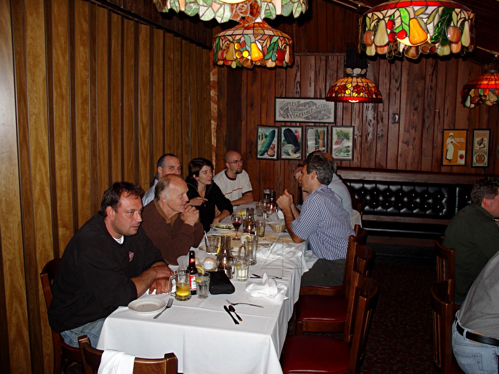
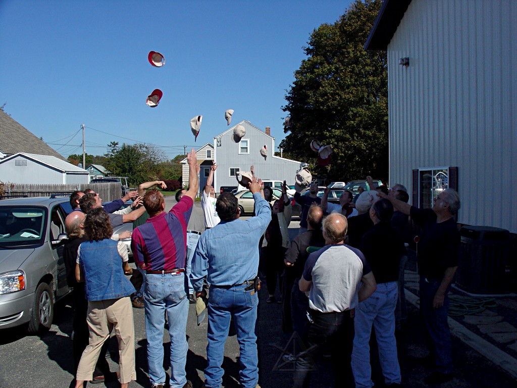
So to dwell more on that people side of things, we all knocked off a little
earlier on Sunday and went up the road for the Big Dinner.
 <-- This was the rowdy section!
 <-- and this was the Birthday Boy...

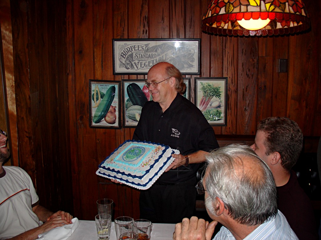
The second of two celebratory cakes that weekend, which Craig somehow
manages routinely to walk around with to show everyone *without* letting
it slide off the cardboard and hit the floor.  Yes, there are outfits that
can basically inkjet-print your graphics onto cake frosting now.  Scary.


Maybe, just maybe, we've partied enough by now ... WOOOOStah!
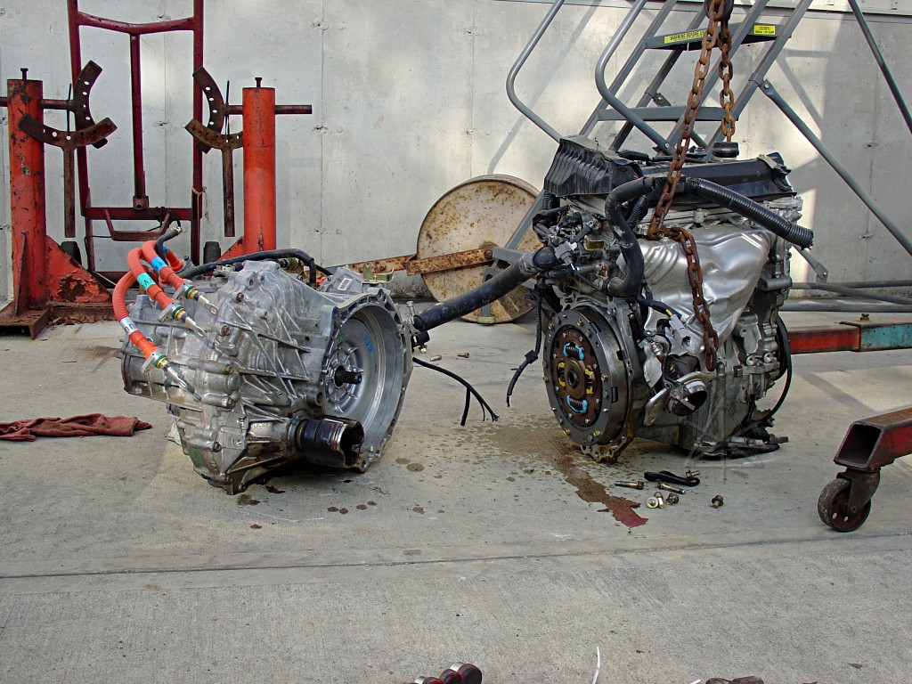
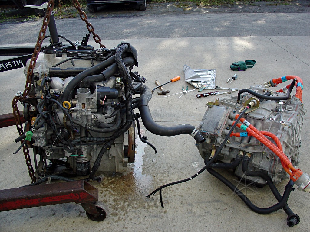
Next morning, back to work, splitting the second crashed Prius drivetrain
[another recent acquisition by Craig].  The transaxle may be recoverable
although some thread points are damaged a bit; the engine is probably
a hopeless mess other than a few isolated parts.  But it's recyclable!
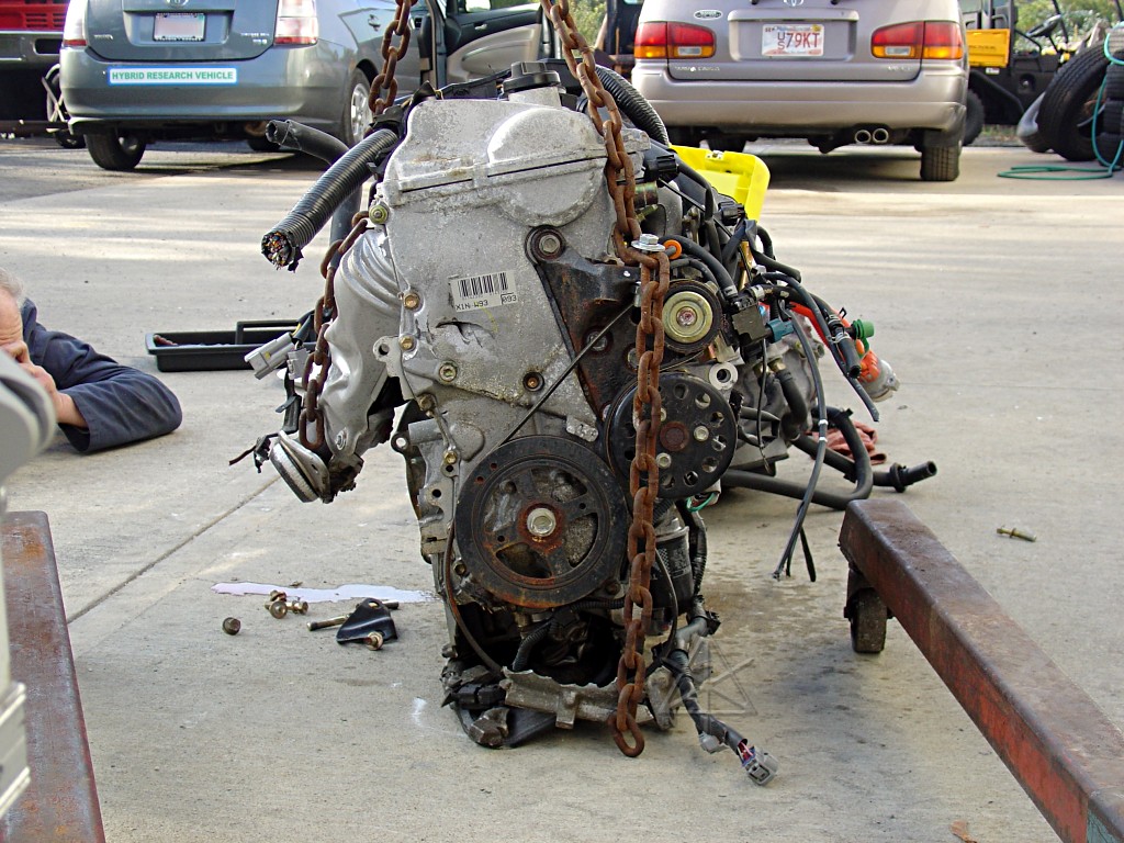
That oil pan and front is totally trashed; I wouldn't trust the block to
not be twisted out of shape too.
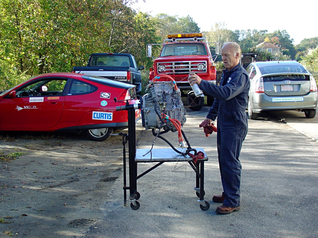
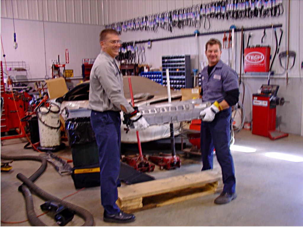
We muscled the transaxle up onto the stand, and went at making it shiny
and more demo-like with Gunk and a hose.

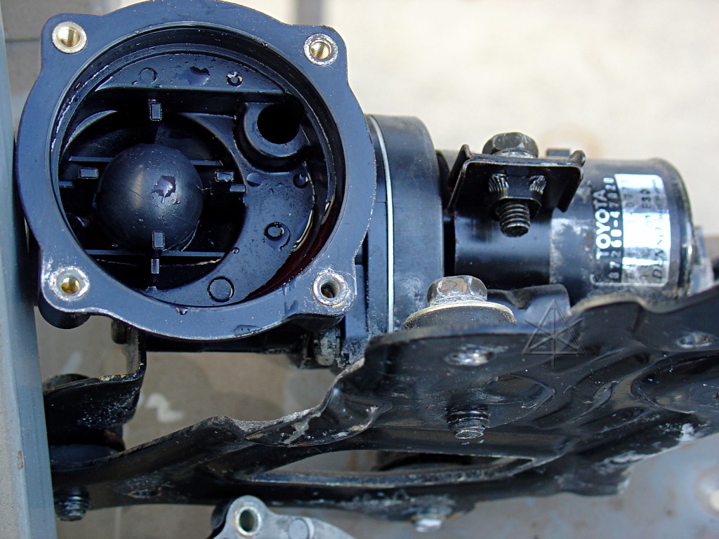
On top of the transaxle we found the auxiliary electric heater-core pump,
which sports not only the impeller housing but also this extra little
lump -- we got curious and popped the cover and discovered it's a check
valve for the coolant.
And around noon, everyone graduated!
_H* 061011