[See text and further story below image.]
|
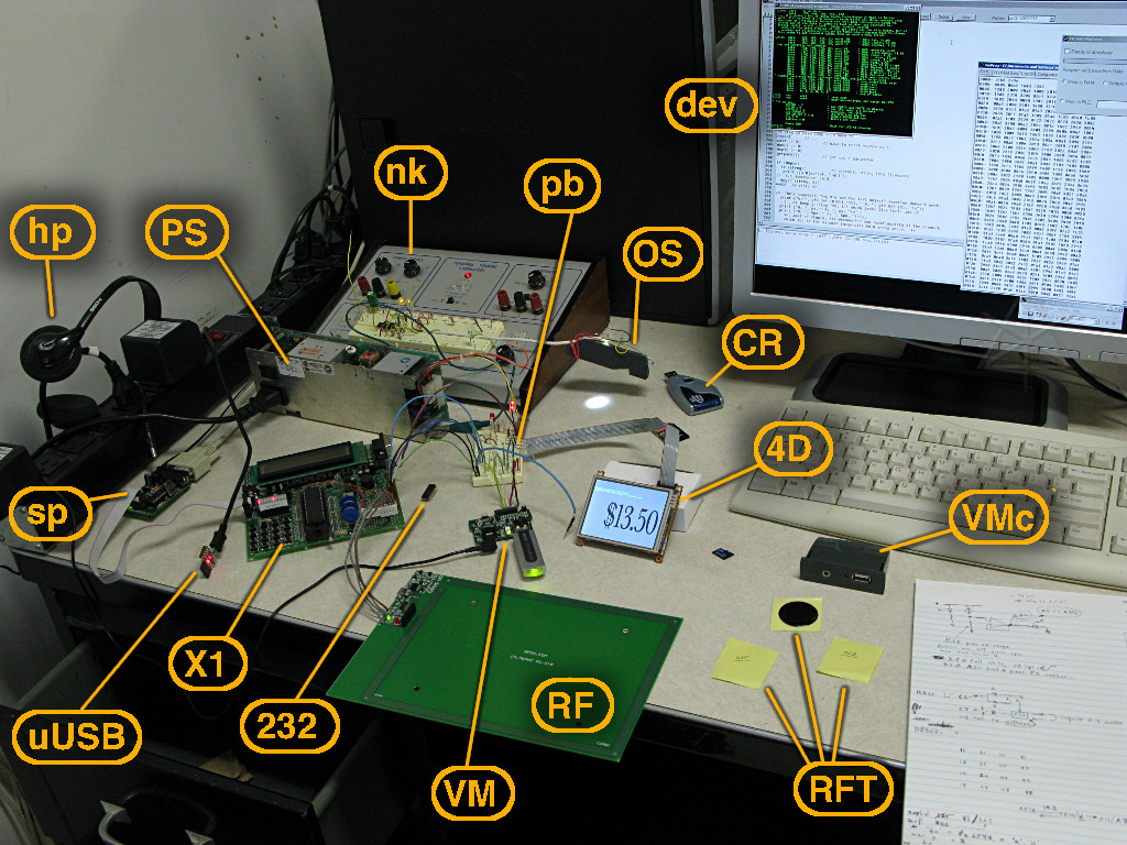
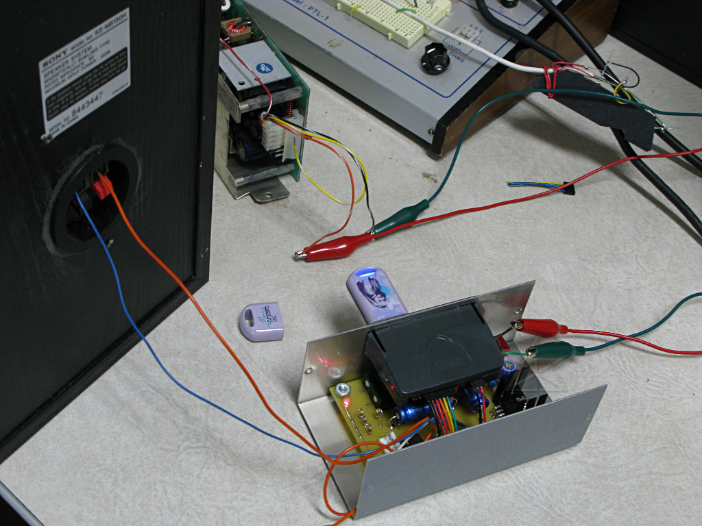
This is my desk at the USS Constitution museum, where I've been part-timing to help develop various widgets to support interactive exhibits. A few different projects are going on here but many of them have common pieces, primarily using PIC microcontrollers to drive other devices and respond to various inputs from visitors.. X1 is a Micro Engineering LAB-X1 PIC prototyping board, which provides a ZIF socket along with power regulation, a two-line LCD display, RS232 port, some trimpots, a little keypad, and a prototyping area. It can also adapt to various types of small serial PROMs. I've added a couple of connectors to the hack area to hook up some other devices. Most of the testing is being done on the 40-pin PIC 16F877, considered sort of a "rolls royce" of PICs because of all the different types of I/O it has and in-circuit flash programmability, and the exhibits director has a couple of sticks of them just sitting around. sp -- The serial PIC programmer widget, that plugs into a special header on the side of the X1. While the X1 itself has a serial port, that's not the programming interface, it's just for the target PIC to talk to via its on-board UART if you want. Programming needs this separate tool, which generates the programming voltage and clocks in the serial flash load from a compiled-up HEX file. PS -- A random 5 and 12 volt power supply we dug up out of a junk drawer, which can run all this stuff without getting hot. The 7805 on the X1 can't really handle the total load, even with the heatsink I added. pb is just a section of proto-board where everything comes together through a forest of solid-conductor wire. This is so far just for routing power and random serial communication around, there aren't any active components on it yet. I back-power the X1's 5V through these connections when using the bigger supply, too. 232 chip: I'm using the UART in the PIC, which by default is connected to the 9-pin serial port through a MAX232 converter that handles rs232 levels. But everything I'm doing is at TTL level, so I had to tap the UART I/O lines and pull the 232 out of the X1 so it wouldn't interfere with the PIC receiving my direct 5V stuff. But that's why they socketed it as a nice big grabbable DIP, instead of using one of the microscopic surface-mount versions. I even had several occasions to put the 232 back in and pull the PIC out so I could convert serial from the *PC* back to TTL to test some things, so it's been pretty versatile all round. 4D is an interesting little toy: a 4D Systems 32032-P1T mini LCD graphics display, QVGA format, 240x320 pixels and a touchscreen. It also has onboard FAT16 file storage, through a socket for the micro-SD card sitting next to it. [2 gigabytes that you can lose in the carpet...] The little programming-environment development kit for it supports displaying bitmap images from files, as well as a few drawing and text primitives. Unfortunately this is not a very mature product, still largely in beta, and it is not at all clear from interacting with the parent company in Australia via their support forum that this product is really still a going concern with them. Trying to program what I need into this thing has been a frustrating nightmare, engendering some fairly biting rants as I kept getting half-answers, non-answers, and flat-out lies from their ostensible support staff. Their development environment's UI is horrendous and broken makes a ton of bad assumptions about the way people work. We're putting up with this as best as we can because they seem to be the only player in the space with on-board data storage capability so far, which is really handy to have in an embedded form like this and not have to throw a beefier computer at the display problem. CR is my little SD-card reader/writer, which takes the adapter [mostly hidden by the grey ribbon cable] that the micro-SD card in turn fits into. This is the way to load image files onto the 4D's little filesystem. The card can also contain compiled 4DGL programs and run a little touchscreen-based meta-selector out of flash ROM on power-up. uUSB The micro-LCD's path to the outside world is a serial interface, and this is a little converter that looks like a USB-based serial port to the PC. This is the download interface for compiled code, but I can't use this to interface to the PIC so in production, the grey cable plugs into its 5-pin connector instead. Power, ground, TTL serial in and out, and a reset line; pretty simple. RF is, believe it or not, an RFID reader [and WRITER, if you want to get into it!], for the 13.56 MHz tags that have become fairly standard. The spec calls for not only a tag unique-ID, but about 64 bytes of user-programmable onboard storage. Most applications simply read the fixed 8-byte tag UID and be done with it, of course. The reader uses a simple serial interface locked at 19200 baud. The astute observer may be asking, "does it work when its antenna loop is flat down on an essentially all-metal desk like that?" ... the answer is no, it has to be picked up a few inches before the tags will read. The simplest way to deal is command the unit into "bulk read" mode, where as long as a tag is in range it will just keep spitting out the UID over and over. RFT are the RFID tags -- little flat black disks with an adhesive backing, to which the paper is still attached because we'll eventually stick them to something but right now I'm just collecting the IDs and building the application's table thereof. I've scribbled my own ordinal numbers on the backing paper to keep them all straight. nk is a typical electronics "training lab" thing, larger versions of which are the infamous "nerd kits" commonly used at MIT. A variable bipolar power supply and chunk of proto-board, basically. It also has some sort of little oscillator and a couple of connectable control pots. The nerdkit is not actually connected into any of the rest of this at all. OS is an early-prototype optical sensor, with the idea being to determine which of a set of objects is underneath. The theory is to shine light onto something [the bright spot on the desk, from a white LED] and measure backscatter with some photoresistors at various angles. The parts are half-ass hot-glued into a block of foamcore just for proof-of-concept playing. This is a separate project, which isn't very far along, but is why in my ship tour page I mentioned optical characteristics of various items fired out of cannons. It's handy to use the nerdkit's variable power supply to vary brightness and photosensor bias levels while still in wild-ass-guess mode on this one. VM is a cute little module called VMUSIC, an embedded MP3 player that reads music files off a regular USB thumbdrive. It has a built-in stereo headphone / line-out jack and takes power and simple serial commands at the rear connector. The idea here is to use it to drive little sound-effect clips; there are other products geared toward this functionality, commonly used in museums, but at about ten times the price. These little guys are less than $30 apiece and depending on how they're driven, every bit as versatile. Vinculum is an arm of FTDI. VMc is a VMUSIC with its cover on. It is designed for snap-in panel mounting, and presents the USB port and headphone jack on the outside. No volume control, however; it defaults to top volume which can be quite the surprise when you snug down the headphones and issue "VPF whitenoise.mp3". Ow. hp Said headphones, which still work after abuse like that. dev Finally, the software side of the development environment. A generic W2K box recovered from some part-time intern's office, onto which I loaded PICBasic and the MELabs support, the 4D language stuff, and a ton of documentation [including the local set of webpages I had to manually generate from 4D's site]. Next will likely be some circuit-board design tools such as a really nice free one from Express PCB [not to be confused with "PCB Express", which is another company doing almost exactly the same thing]. That made for an interestingly confusing afternoon when I went to start chasing down this stuff. |
So, what's it all for?
|
[ ... I hear you ask ... ] Well, as I said, various efforts, but
what's on the desk here is mostly for one in particular which despite involving
the most disparate parts and coding is the most likely to get finished first.
The RFID tags get attached to cards showing various items that a sailor going
to sea would have to buy for himself back around 1812 or so, usually from the
"Purser" on board the ship. Everything a sailor owned was kept in a "sea
bag", so this is an activity to fill one's sea bag and see what items would
cost and match it to how many months of pay that meant at the time. Remember,
this is back when ten cents was a big deal -- a sailor's pay was on the order
of $17/month.
So we need to buy items, by picking up the cards with their pictures and labels, and dropping them into a "sea bag" sort of construct which happens to have the RFID reader located at its neck. The tag UID goes to the PIC, which looks it up in a table that also contains the item number [that's our SKU, so to speak] and a price. The item number is turned into picture filename and sent to the 4D screen, which displays the item picture to confirm the purchase. A few seconds later our running total comes up, also displayed as a set of image "slices" as we see here, using a nice old-fashioned font since the 4D's built-in fonts look like ass. In the pre-production version the 4D unit can also emit a tinny little "cha-ching!" [yes, really, I found an appropriate WAV file] out a tiny speaker on the back. What's really scary is that the Store 24 near the Museum has cash registers that play *exactly* the same fake cash-register noise through a speaker. I almost freaked when I heard it, especially after the hell I went through to get something that would actually play on the 4D unit. Not all .WAV files are the same, by any means. The VMUSICs aren't involved in the sea-bag, and the ka-ching will probably go away for the final version since it's not exactly period. But we imagine that they will be worked into several other things that play cannon booms, tell stories, issue bloodcurdling screams of dying sailors, or whatever. They can be driven off tiny little 8-pin PICs that only have to monitor a couple of switches and issue one or two ASCII commands at 9600 baud. None of this stuff is my idea, by the way. I'm taking the reins on various projects that the director and his crew have been working on for some time, organizing the pieces that they'd already sourced to work with, and shouldering some of the workload to check it out and put it all together and write bits of code. But it's being a good learning experience for me because I've never really done PICs even though I mostly understand how they interface to their environment. Modern microcontrollers are astoundingly versatile, with the ability to reconfigure arbitrary pins as TTL output, PWM output, digital input, A/D input, etc. I think it's that "analog" aspect of a couple of the projects that the Director is a little less sure of and is looking to me to make sure things will get designed and hooked up in a robust, "museum grade" way.
|
_H* 090414
|
As expected, some board design started happening soon after the above was
detailed. One obvious general-purpose "PIC makes stuff happen" board looks
rather like a centipede in its trace pattern, holding a 40-pin socket for
the 16F877 and breaks out a bunch of the I/O into an easily-interconnected
patch area similar to the Lab-X1 kit itself. Besides wanting a small handful
of those boards for overall control versatility, we're also looking at up to
a dozen small interactive exhibits that involve audio clips, so a design for
a dedicated audio board that has a small but fairly capable amplifier included
is needed. The VMUSIC modules can drive headphones reasonably well by
themselves but some of the interactive stations are going to need a bit more
volume as speakers in some of these things are likely to be at a slightly
greater distance from listeners' ears.
There are many different audio-amp chips available, but once the additional criteria of small, simple footprint, single supply, and minimal external parts are applied, the field of choices becomes much smaller. Many of the classic small TDAxxxx packages seem to be deprecated and out of stock lately. After reading many spec sheets I've settled on the TFA9843, which meets most of those requirements and comes in a simple package akin to an overgrown TO-247 with nine pins, easily heatsinkable off the edge of a board without an insulator. Next task is to wrap a board around it, including power for the VMUSIC and a tiny, self-clocking 8-pin PIC to drive it.
Each picture below links to a fullsize version which shows the detail. |
|
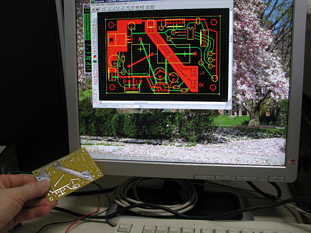
Routine printed circuit board design has become quite automated these days,
while I've been rather out of the loop on the possibilities. ExpressPCB
gives you a very straightforward downloadable CAD program which can also
directly submit the design as a manufacturing order including payment by
credit-card. Still, it's a bit surreal to spend a while noodling up a layout
in a graphics program [see big pic] and then two days later, hold the finished
object in your hand. And it's complete with fully plated-through holes and
all pre-tinned traces and pads which makes assembly a breeze.
This is one of ExpressPCB's "miniboard" types, which is constrained to a fixed size, limited in number of holes, and doesn't include solder masking or a paint-graphics layer but is by far the cheapest option. Three copies of the board for about fifty bucks, and no need to stain one's fingers with ferric chloride and wonder if the etch resist will hold up. Arrrr, the good ol' days. |
| My screen wallpaper at the time is this, a big magnolia nearby in the Navy Yard which I happened to catch while it bloomed like this for about a day. Petals were already falling off in great numbers that morning, augmented by a fairly strong breeze, and by the late afternoon when I headed home, most of them were down and curled up brown on the lawn. |
|
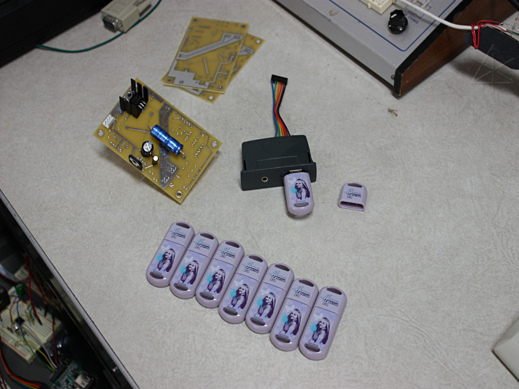
My boss has an open account at TigerDirect, so in the meantime he fished
around there for cheap USB sticks to use on these projects. Here's what he
came up with to buy in volume: themed thumbdrives from Disney with a "Hannah
Montana" graphic over a delicate lavender background, five bucks apiece. Well,
whatever. Theory is that nobody's ever going to see these, they'll be buried
inside an exhibit cabinet. I had to look up what the name refers to, because
I don't track pop-culture and frankly had no idea even after looking at the
promo-kit files that come preloaded on the sticks. Hannah Montana
*wallpapers*??! No thanks, I'll stick with my own springtime shots of
magnolias and turtles.
Assembly has begun on the first board here, mostly to check parts fit. I did okay for my first ground-up design effort; everything fits as expected. Including the power-amp chips which have a strange pinout at .1" spacing, but offset by .05 between the rows. But it was easy to create a "custom component" for this to augment the extensive ExpressPCB parts library. |
|
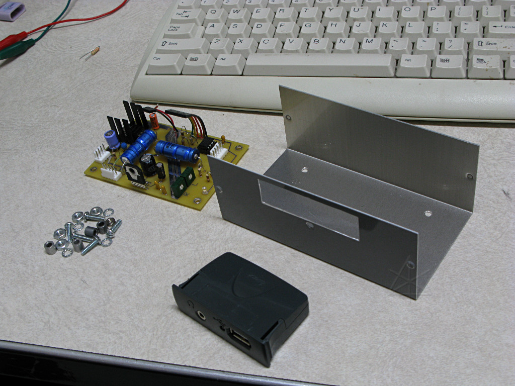
I dug around in my piles of crap at home and came up with a classic aluminum
"BUD box" that happens to fit everything rather nicely, including the VMUSIC
module clipped through a dremeled-out slot just above the amp chip where
I wanted it. The amplifier simply heatsinks to the side of the box just
underneath, and the colorful little 2mm-spacing harnesses that come with the
VMUSICs all get chopped in half, stripped and tinned, and used to connect the
module to the amp board. A handful of hardware mounts the board standing
off from the bottom in a slightly old-school but functional fashion.
The elegant fit into this box has since driven a decision to order more of them as the best way to mount and enclose these units. Making the slot for the VMUSIC is a little klunky and tedious, but worth the effort to hold it in just the right place. |
|
External hookup to the assembled whole is simple, via standard Molex pin
headers: power in, speakers out, and triggers. Play levels for right and
left are independently set by the small pots sitting just under the VMUSIC
housing. The connector sort of under the speaker wiring is for the trigger
pins -- raise one of the three to +5V to have the unit play
001.mp3, 002.mp3,
or 003.mp3 from the stick's FAT filesystem. A stupid-simple program on the
PIC just watches the lines, debounces them, and sends the appropriate ASCII
command to the VMUSIC. All of the personality of each exhibit, including what
gets sent to which channel which may be completely different for two separate
listeners, is in how the MP3s are put together.
The two amp outputs can also be bridge-tied for higher power into one channel, as one is inverted from the other and you have to flip one of two speaker hookups for proper stereo phasing. In [very very after-hours at the office] testing I ran full-volume white noise through both inputs and a bridged output for several minutes; the side of the box where the amp's baseplate face is screwed down got mildly lukewarm but that was about it, and cooled down almost immediately once the abuse was over. The output power isn't up to the level of a simulated cannon boom or anything; we'd need a bigger rig for that, but this little guy can certainly hold its own as far as making noise. |
| All is not completely rosy at this point, however. When the unit goes idle I notice a soft but distinct high-pitched whine in the output -- enough to be annoying especially considering that these things are going to be up and running all day as visitors come by. We don't want them to hear anything until they start interacting with whatever the display is. Mind you, I'm not using the "mute" facility on the amp chip although I could have with a couple more parts and a spare GPIO from the PIC, but that adds the problem of needing to know how long an mp3 plays, and I figure that with everything this close togther and the ground-plane pseudo-shielding running from the VMUSIC outputs to the level pots there really isn't much opportunity for noise to creep in. But there it is, and it sounds radically *different* before and after the VMUSIC has played any file! Careful diagnosis with a scope in two-channel differential mode hints strongly that it's some sort of ground-bounce issue coming from the VMUSIC itself and caused by its processing elements, but I would also readily believe that it's affecting the output because I may not have laid out my grounds quite right. |
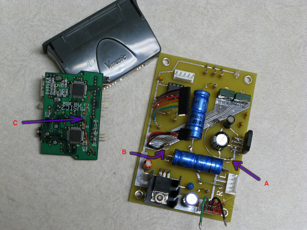
| So here comes our second and harder lesson in low-noise board design, where various patches get kludged into our test prototype. [Refer to the big pic.] | |
|
A
is a jumper tying the major ground areas for input shield and amp together.
After a little experimentation it's pretty clear that the noise is coming
from the VMUSIC itself and not the PIC, and it's known at this point that the
VMUSIC with a thumbdrive inserted draws a healthy amount of current which
could make the ground reference out near where it connects slightly different
from the one going to the amp. So the separately-routed grounds become more
of a single plane here.
B is bringing a second ground lead up to the VMUSIC, using a pin provided between the two line-outputs on the module at the smaller connector. This is electrically the same ground as the power ground in the other connector, but if the whole unit is drawing significant current to a processing element through a single tiny wire in the connector then the ground reference could easily start bouncing up and down a little. Anchoring the ground more firmly through this second lead helps suppress the noise quite a bit, in fact. |
|
Close examination of the VMUSIC reveals that the visible planes on both sides
of its own board are both ground instead of power and ground, but the two are
connected only by one or two tiny vias near the edge. In fact the ground
supply lead comes up and gets connected to one plane, and then way down by
the other corner of the board is a via connecting the two planes together
and then that second plane finally comes back over to be the audio out
ground reference. Meanwhile, all the rest of the circuitry is pulling
current away from the path. Oops. Arguably, a questionable layout on
the part of the VMUSIC designers who evidently didn't note that some USB
sticks draw over 100 mA by themselves. Making an additional jumper at
C
gives an extra and more direct connection from the incoming power ground
to the audio reference, and by itself also helps stabilize the VMUSIC ground
substantially.
Basically, it's a textbook ground-loop problem although at something other than 60 Hz. | |
|
It turns out that fixes A and B are sufficient without having to hack each
VMUSIC module as well, so the revised amp board CAD file has an update to
increase the ground-plane area and provide another hole for a ground
connection into the VMUSIC's output harness. The idle noise is still there
just a tiny bit if one listens very closely at high gain, but it's
acceptably low now.
Fortunately only the initial batch of three boards need to be retrofitted; the rest are ordered to the revised spec. |
_H* 090526
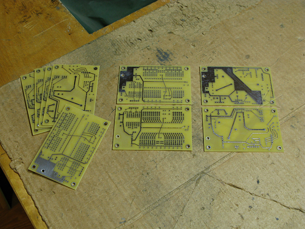
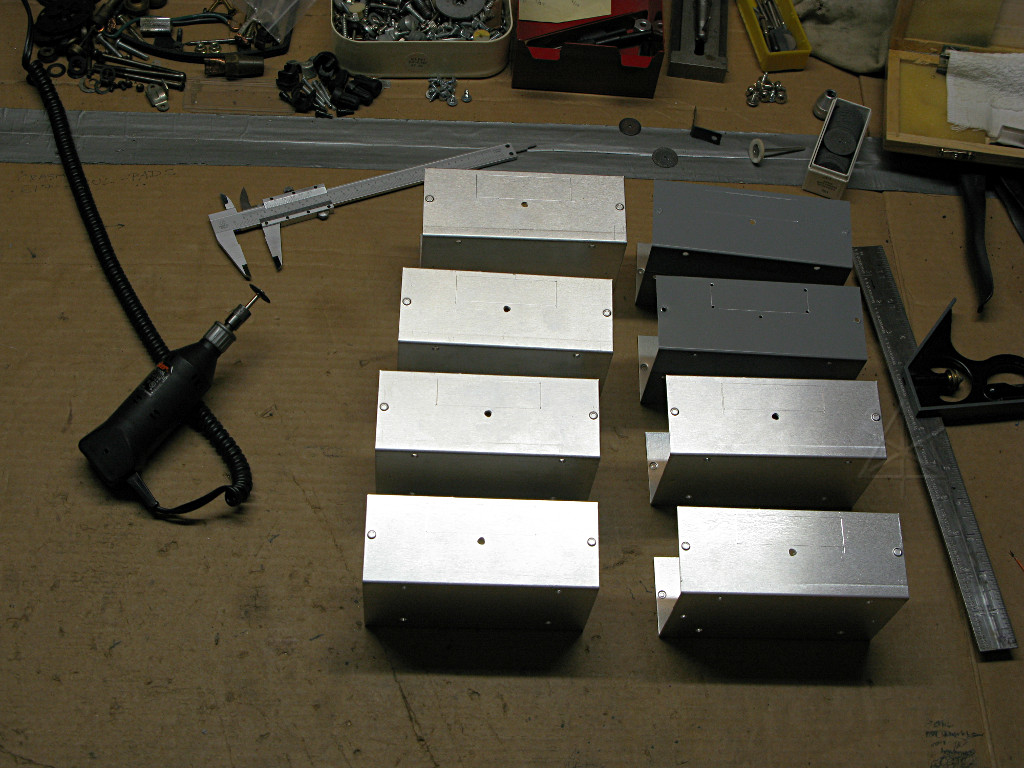
| A few days later the remaining circuit boards arrive, including the set of 40-pin PIC carriers for controlling the more complex exhibits. Other backordered parts also finally dribble in and land on my desk. Now it's time to go into bulk production, particularly on the audio units. |
|
At the right is the reworked audio board, front and back; in the center is both sides of the generic "massive I/O" PIC board. The latter is right up against ExpressPCB's limit of 360 or however many holes for their "standard miniboard", so to also accomodate a quad op-amp and its fairly generic surrounding patch area I've had to eliminate some of the power-rail attachment points along the edges. That's okay, the whole idea is that various hardwire-patching will occur to complete any given design on these. |
|
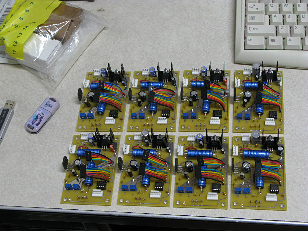
An evening of bangin' through a bunch of them, assembly-line style, yields eight more amplifiers with their VMUSIC interface harnesses ready to go. |
|
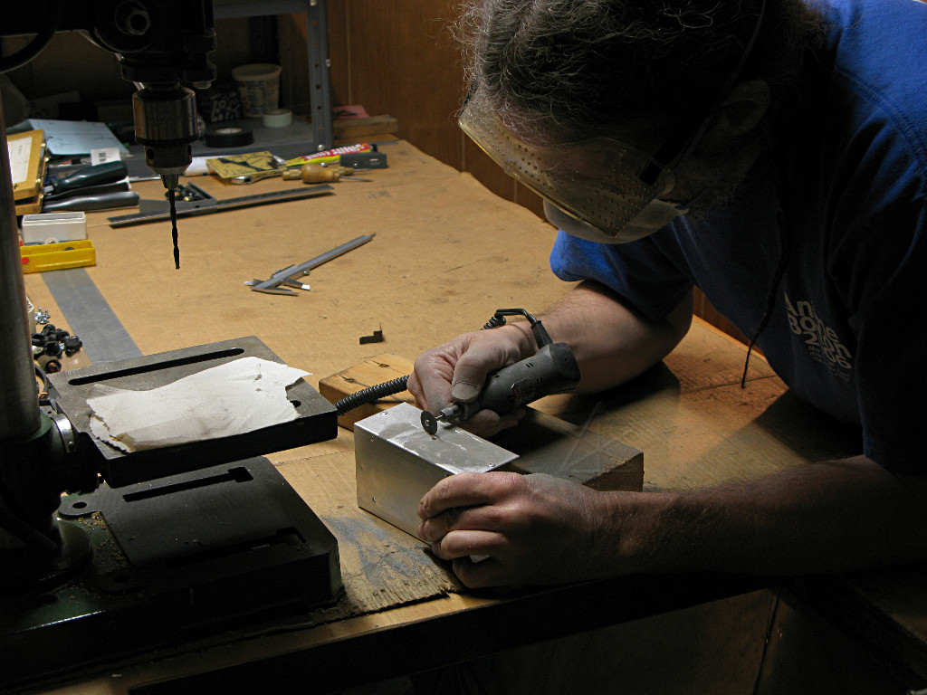
Here's the part I'm dreading: having to slot up all those additional BUD boxes we ordered. The positions for drilled holes and slot edges transfer fairly quickly using a paper template, but now I've got to dremel out all those edges and knock out the middle. |
|
So I just grab the breathing-mask and goggles and grind my way through it, so to speak. It only takes about half a morning to get past the messy bits and trim all the edges nice and smooth with a file, and amazingly none of the results are inordinately "off" despite the questionable spindle bearings in my drill press and hand-working all the carbide-wheel cutting. |
|
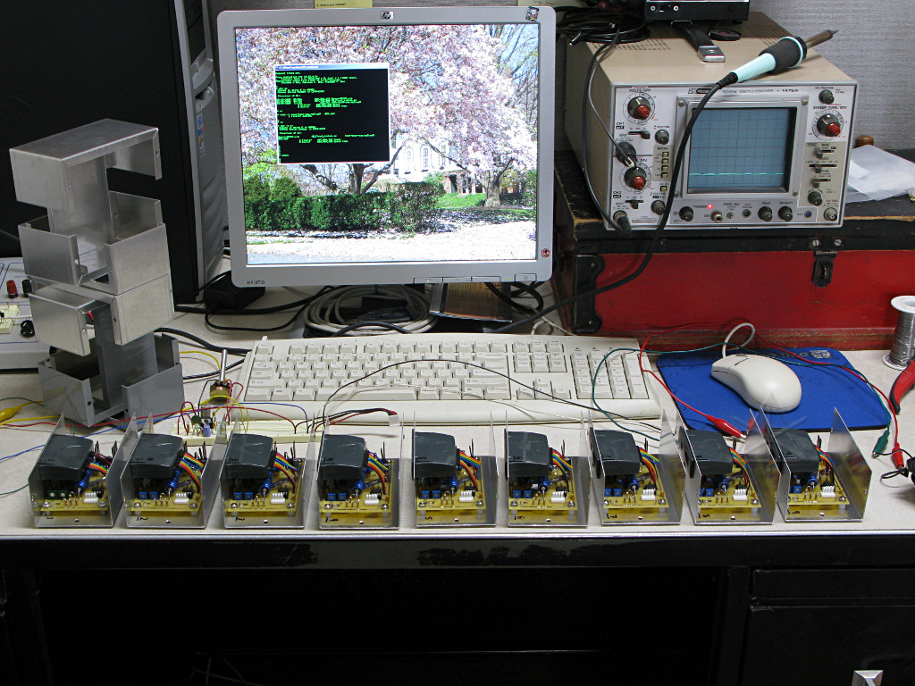
The end result a little later on is nine completed units with their mp3 modules inserted and the PICs all programmed up. They're even serialized, to more easily keep track of any parts that might be bad. And one can create entertaining cubist art projects with all the box lids. |
|
Final testing turns up a couple of problems. One of the VMUSICs actually has *solder bridges* across a couple of its chip leads and doesn't work at all, leading me to wonder why the F it's got a "QC pass" sticker on it??! Actually it's clearly *trying* to work -- when commanded, the LED next to the stick blinks as though it was playing the file, but I notice that the blinking stops much sooner than it should have for the length of track and nothing emerges from the audio. Aha, I thought, maybe some sort of clocking problem where it's not correctly pacing the mp3 decoding. Which is what actually leads me to open it up and do a close examination rather than simply sending the thing back to Jameco. This one's clearly suffered from a bad wave-soldering job in general, but scraping the solder blobs away between the three leads in question fixes the problem and it's good to go. |
| Another little problem is that one of the 12F675 PIC chips fails to command its unit. It turns out that its little onboard oscillator is actually too fast and clocking out serial bytes at something more than 9600 baud -- its burst is visibly shorter by comparison on the o-scope, in fact. For now I set this one aside and just swap in another PIC, but these chips have a nonvolatile calibration register that one can play with to tweak the oscillator speed so I'll go back later and see if I can "bend" that one. | |
| Livestock was frequently brought aboard ship back in the day as a convenient means of preserving meat, and a normal loading method was to suspend the animal securely in a sling and hoist it aboard via rigging attached to a yard overhead. Some piece of the exhibit team's creative process latched onto this as a feature they wanted, i.e. to have not only some sort of critter swinging in the air, but also able to make noise upon having its sling rigging moved by a museum visitor. I gather that the early thoughts on this were "can we put a car battery and a sound system inside a cow, and fly it?" |
|
Something the size of a cow was a bit infeasible, but a compromise had
eventually been reached that would bring the project to a manageable scale.
What do you need to sling a flyin', singin' barnyard animal in the air with
just rope and no wires? A sling, obviously. A car battery, or more properly
the SLA innards of an automotive jump-box which is less likely to leak. An
audio player system of some sort, which I now conveniently had nine of ready
to go. A small but decently full-range speaker, courtesy of Cambridge
Soundworks and the guys over in the shop who weren't using that system
anymore. Some sort of motion trigger switch, detailed later.
And a goat. |
|
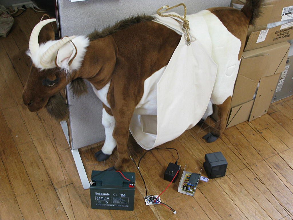
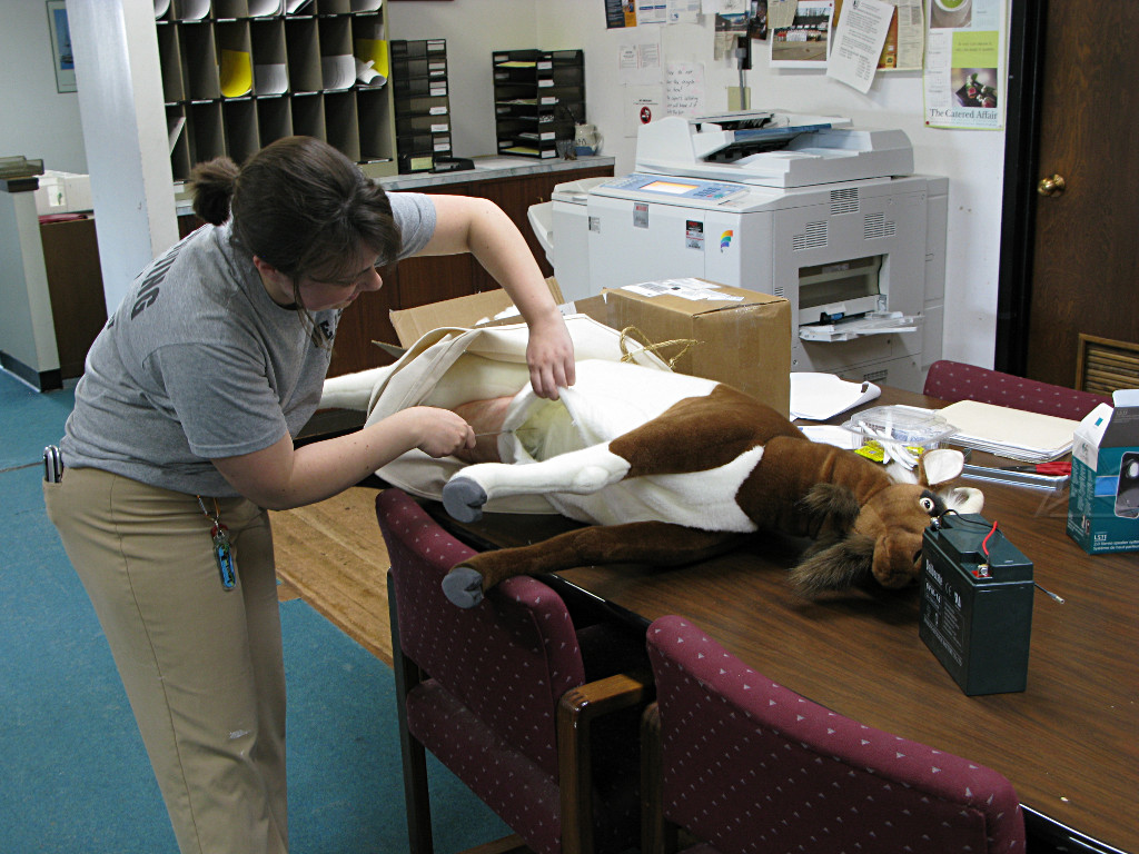
This goat had been standing around in an office lobby the entire time I had been at the Museum, not really being dealt with, but now as crunch-time approaches it's time to start some exploratory surgery at the very least. Another exhibits staffer is tasked to slice open the goat and start removing its original innards. The goat's got a great expression here, staring fixedly at the battery and obviously thinking a terrified "you're going to put *what* into my belly?!" |
|
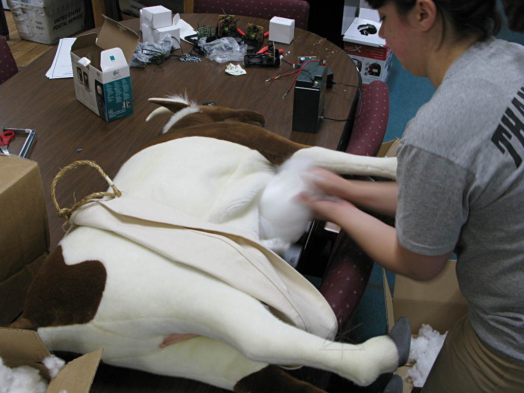
The interior is mostly big wads of poly fiberfill, as might be expected. As we delve deeper it turns out the goat actually has a welded steel skeleton, so it's clear that because the battery is fairly heavy and the belly cloth is unlikely to gracefully contain that on its own despite the sling underneath, that I'll somehow tie the battery up to the interior spine for additional safety. |
|
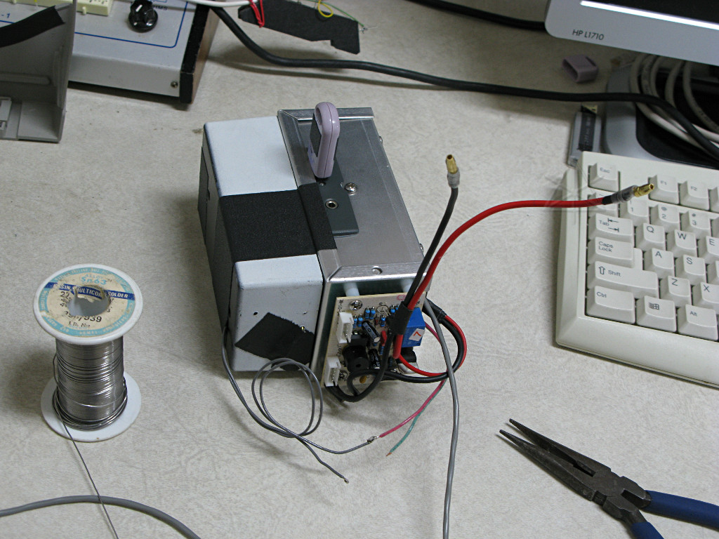
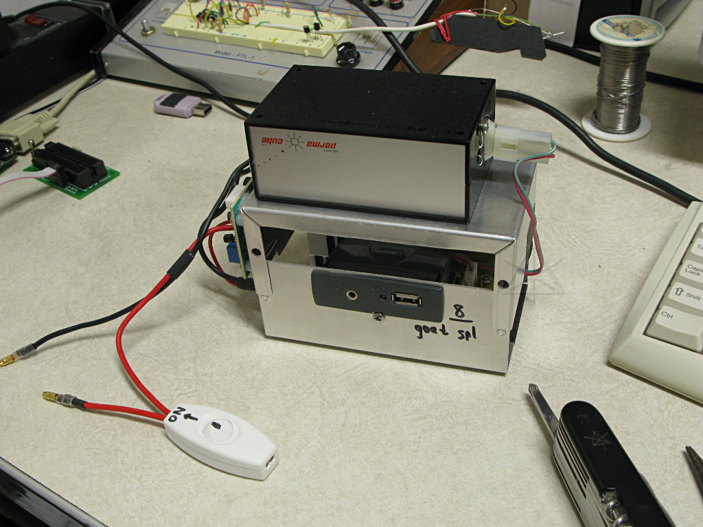
The audio box gets married to a primitive motion detector from some long-bygone
project that contains a swinging magnet and a reed switch. It seems to work
well enough for this purpose. The original jump-box charging circuitry gets
mounted on one end of the lid. Right here is more justification for using
those aluminum BUD boxes, since it's so easy to drill a few more holes and
hang additional stuff onto it.
This lashup totally looks like a bomb, and it's about to be stuffed into the butt of an innocent goat. |
|
It all fits reasonably well, in fact. The battery occupies most of the
torso, suspended on a creative but secure sling constructed of nylon rope
and gaff tape. The audio box and switch rests above the udder, which seems
to be a separately padded unit, and the speaker nestles nicely into the chest
between the front legs which gets the sound directionality a little more
realistic.
The flow of bad goat puns from people passing by the meeting table while we're working on this is pretty impressive. |
|
The next problem is finding a suitable sound effect. It turns out that there
are numerous websites offering free and unencumbered samples of animal noises,
some of really awful sound quality and some acceptably usable. Some examples
are wavlist
and free-loops and
soundbible, and
a quick search turns up many others. Most of them seem to be in .wav
format, requiring conversion to MP3 for the VMUSIC.
But in exploring these resources, the creative process begins to go rather
awry and I decide to have a little fun with this as long as we're still in
sort of a pre-opening state at the exhibit. I have the template PIC code to
play several different MP3s depending on which pin gets triggered, right?
A five-minute mod and reflash changes this particular one to be able to play
a randomly selected one of four files from the single trigger, with the
randomizer constantly churning in the switch polling loop so the choice is
entirely driven by when the goat is poked. The result is that once the goat
is turned back upright and wiggled, it makes anything *but* a goat noise:
|
|
It gets hung in place later that morning, flying above the entry stairs
to the new gallery, with the "animal farm" data stick and a fresh battery
charge. The pre-opening reception is that night, and as I expected, those
present find the variety of sound effects hilarious.
Unfortunately, something about the motion switch [and its taped-together internal nature] drifts over the course of the evening, causing the goat to work less and less reliably and naturally causing event attendees to yank even harder on the pulley ropes to try and elicit a response from it. This switch also has motion-axis directionality, i.e. if the yank is along the spine-line it doesn't trigger at all. Obviously, this old switch won't quite do and needs to be re-thought. |
Sensitive new-age livestock
| I wake up one morning over the following weekend with an inspiration. The switch needs to be independent of a slight tilt offset, and reliably responsive to any axis of sideways motion. The answer is a set of concentric pendulums: one as a tube that swings, and another small rod that swings inside that and any meeting between them must complete a circuit. So the parts must be metal and whatever joins the two together must be an insulated spacer. |
|
A bit of junk-closet [*] scrounging turns up a rubber stopper, a section cut from an old ski pole, and a box that once housed some ancient and undoubtedly wikkid-high-tech for its time piece of photographic equipment, along with random other parts. Copper wire is carefully bent and soldered into eyelets once installed in a hole drilled through the center of the stopper, and very small and short screws secure the stopper into the top of the tube but keep things insulated. A flexible wire harness will connect the two elements out a typical Molex connector. |
|
* [Who the hell am I kidding? Junk *house*, not junk closet. I have way too much of this kind of crap laying around and still largely unorganized, and it's nice to find opportunities to usefully use up some of it now and then.] | |
|
The assembled swinging apparatus hangs from a small hook bent from a paper clip, and is completely independent of external tilt over a generous range before the tube hits the inside of the box and even then it's still pretty sensitive. The small weights at the bottom of the previous picture turn out to be unnecessary and in fact bad because once they're attached, the swing periods of both pieces are roughly the same. Leaving the end of the inner wire bare has the periods radically different so it's just about impossible to carry this thing across a room without hearing several clinks from the tube being hit. |
|
The connection pulse from the wire bouncing off the tube is on the order of microseconds, *way* under the 20-ms debounce guard time coded in for the audio box trigger. In this case the poll time is shortened to one millisecond, which is still an eternity for a 1-MIPS processor and still much longer than the pulse actually given by the switch. Cobbling in a capacitor across the input pull-down stretches that tiny pulse to something close to a millisecond, and now it reliably triggers any time the switch connects. |
|
The "audio bomb" is rebuilt to accomodate the new switch, which also changes
the whole mounting orientation by 90 degrees. Because of how the interior
skeleton feeds into the goat's back legs, it won't fit without being moved to
the very back end of our poor victim, but I finally manage to lodge it in
there. At this point I decide to keep the battery charging wall-wart external
and just run the 12V supply up to another Molex that can be discreetly tucked
under the sling when not in use.
While the "animal farm" was amusing, it's now time to scrounge up a suitable goat noise track and install it on the thumbdrive. The Director and I review various samples off the net, and both of us listen to this one and immediately agree "that's good, let's use it". It's short and nicely punchy, and sounds really good over this speaker. |
|
The assembled unit also gets a battery on/off switch which is still buried
inside partially due to wiring length, so must be turned on and left on as the
belly is hack-job sewn up with a length of old wire. This means that as I
carry our fuzzy li'l friend out to the exhibit area to re-hang, it is bleating
its way continually down the main museum hallway for the amusement of several
visitors there at the moment, and the entire time we're re-rigging the sling
and internal safety rope that emerges through the goat's back and bears the
weight of the battery and spine. It is amazingly coincidental that the swing
period of the entire goat and sling and yard-arm loop is such that the switch
generally does *not* trigger, requiring an actual abrupt movement at the
pulleys to make the noise.
The effect is marvelous at the next reception a week later, surprising a lot of people who don't expect a stuffed goat to actually make a realistic noise when lightly disturbed. | |
| Future improvements could include a "micropower" standby mode to shut down all but some minimal detection circuitry after some timeout, but this would make it so that the first visitor to haul on the rope would not be rewarded with an immediate bleat as it takes a full five seconds for the VMUSIC to boot, read the stick, and be ready after application of power. The whole rig draws about 120 mA when powered and not playing, dissipating about a watt into the goat's innards [which actually does get the unit mildly warm as it's cozily insulated in there, hmmm...] which with an 18 amp-hour battery is still good for several days. On the first run it lasts almost a week without charging, with the battery down at 11.6 volts when un-slung for the improved tremble switch. What probably makes more sense is a simple addition to museum nightly closing checklists to put the goat on overnight charge a couple of times a week which should be sufficient to keep it going. |
_H* 090613

|
Some of these may get a more extensive writeup later on, but for now just bear a brief mention. Boston-area folks are encouraged to just go down there once the "All Hands on Deck" interactive learning gallery is publicly open and see this stuff for themselves! There is a lot of fascinating information around the Museum in general, and at the time of this writing I haven't even had time to go around and take it all in myself. |
|
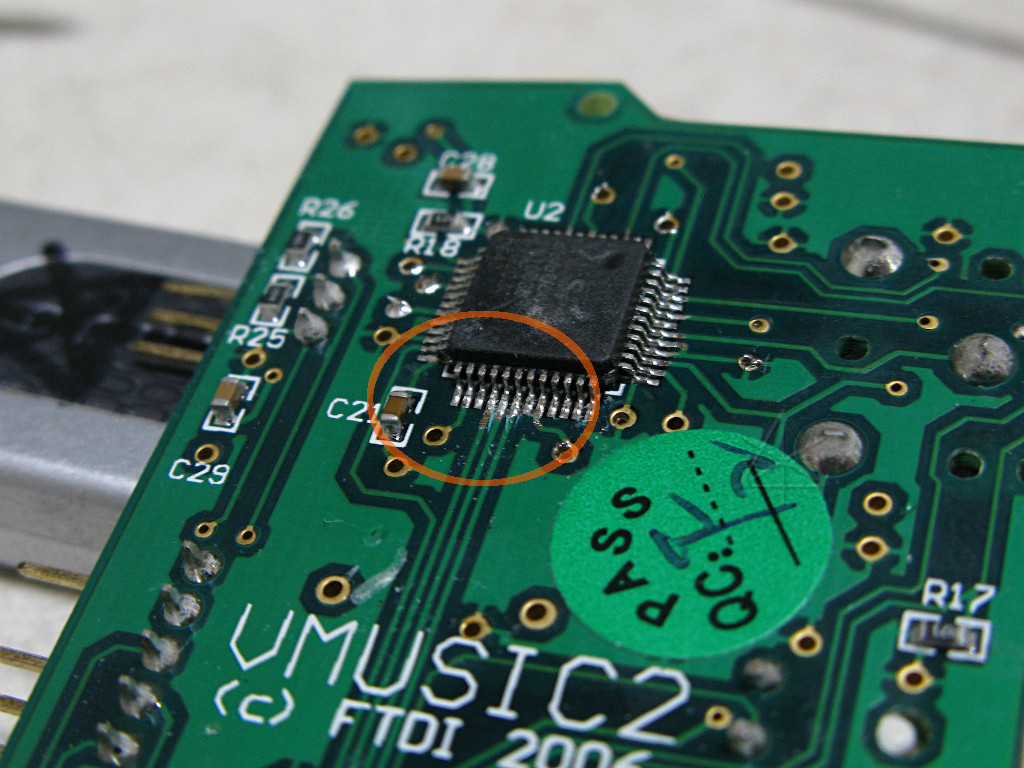
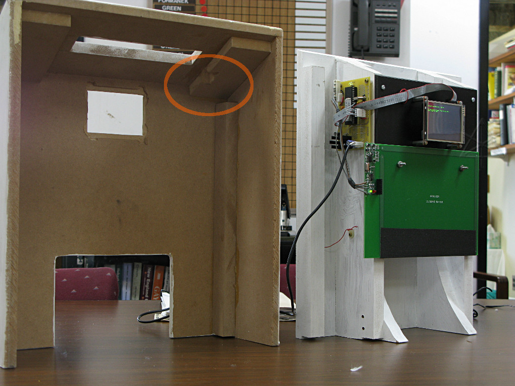
This is an early rev of how the "seabag" purchasing activity worked out. All
the same parts with the first of the big PIC boards running things instead of
the Lab-X1, and the set-shop folks came up with a relatively simple MDF housing
with a "chute" to drop item tags through. The tags simply land in a small bin
underneath, facilitating easy use by the next visitor rather than having an
actual *bag* from which tags would have to be retrieved before using again.
An additional notch had to be milled out [circled] to accomodate the board as I didn't realize how tight things fit before mounting it. The RFID reader ultimately got moved to behind the chute instead of in front because in the configuration shown here it's too easy to trigger a spurious purchase from in front of the box. A bit of klunky tinfoil shielding is also necessary on the inner face of the cover, which does more to simply reduce overall sensitivity rather than apply any actual directionality as the wavelength is still 22 meters or so. But this piece is finally working well enough to be publicly usable -- it far and away involved the most coding to get all the pieces talking to each other. |
|
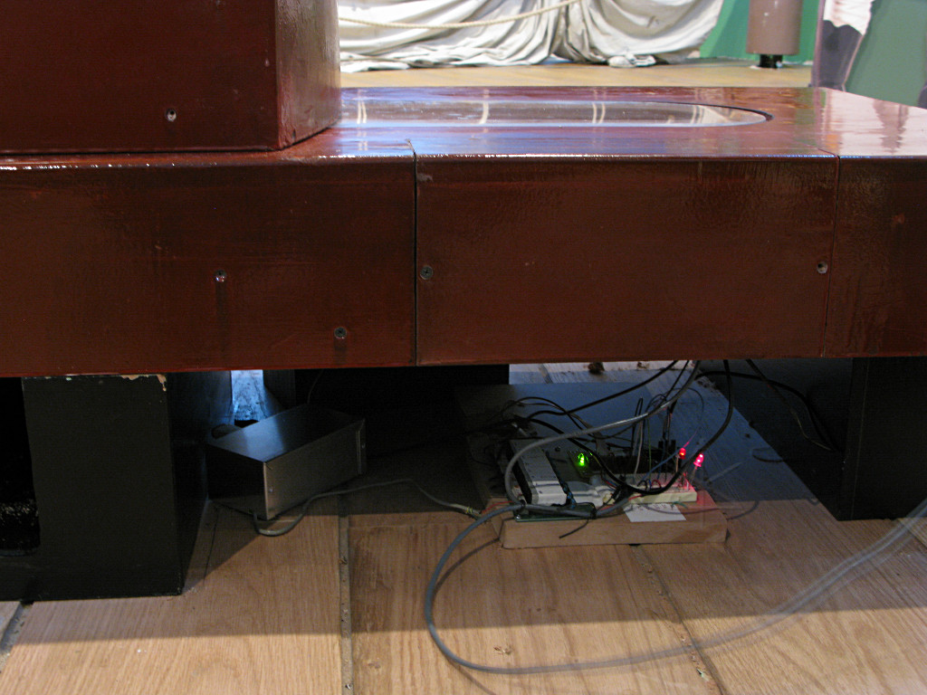
Then there's the carronade, which is a whole 'nother can of worms. The idea
is to have a working simulation of one of the shorter, heavier-load guns that
lived up on the spar deck, and run visitors through the entire gun drill
including loading, running out, and "firing" using actual physical pieces
[but something lighter than a 36-pound cannonball]. If they get the order
of operations wrong, a video display would tell them how to try again.
The embryonic design involves an air-cylinder to produce recoil of the entire top half of the carriage, a way to return the loaded parts to a hopper for the next person, and of course numerous safety switches all over it as well as some unspecified method of object sensing. It is nowhere near done yet, and the early rev is sharply showing the downside of using MDF construction as it's basically cardboard and not actually that structurally strong and starts falling apart under repeated stress. |
| For another one of the pre-openings I threw together this hack-job controller to do some minimal steps of sensing the switch inside a recreation flintlock as its rope is pulled, firing the air solenoid valve for the right amount of time to move the carriage, and triggering a reasonably loud BOOM from an audio widget hooked to a random speaker scrounged out of the Museum's storage bay. It's somewhat impressive as people don't expect the thing to move briskly backward like that, but this is about as far as it's gotten and isn't ready for public consumption and definitely not safe for kids yet. Much more engineering needs to go into the implementation in general. | |