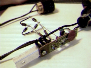
Underside view showing the extra .02 capacitor tacked on across the original cap.
I now *finally* understand why most residential dimmers exhibit that
annoying "pop-up and then dim down" behavior and refuse to just come on
linearly from the bottom like you'd want.  I've spent most of today
noodling around with a bunch of cheapo dimmers, figuring out more about
how they work and why they have the quirks they do.  This gets fairly down
and dirty.  Well, this *is* a mailing list for techies; you asked for it.

I refer the astute reader to

   http://www.hut.fi/Misc/Electronics/docs/lights/lightdimmer.html

[or google's cache thereof, if this is broken] for a little background and
some excellent discussion of dimmers, lamps, and causes for numerous problems
one might run into with them.  Except the ONE thing I was really looking
for -- it is mentioned briefly as a quirk, but not explained electrically.

Excerpted from that same document [and several others found in the same
google search -- not sure who stole from who, but they're all the same]:

   Minimal circuit

   This is the type of common light dimmer (e.g., replacements for
   standard wall switches) widely available at hardware stores and home
   centers.  This circuit uses slightly different component values than
   the previous one and does not have any radio frequency interference
   filtering. This one contains just about the minimal number of
   components to work at all!

    Black o--------------------------------+--------+
                                           |        |
                                        |  |        |
                                     R1 \  |        |
                                  185 K /<-+        |
                                        \  v CW     |
                                        |         __|__ TH1
                                        |         _\/\_ Q2008LT
                                        +---|>|   / |
                                        |   |<|--'  |
                                    C1 _|_  Diac    |
                                 .1 uF --- (part of |
                 S1                     |    TH1)   |
    Black o------/ ---------------------+-----------+

   S1 is part of the control assembly which includes R1. The reostat, R1,
   varies the amount of resistance in the RC trigger circuit. The enables
   the firing angle of the triac to be adjusted throughout nearly the
   entire length of each half cycle of the power line AC waveform. When
   fired early in the cycle, the light is bright; when fired late in the
   cycle, the light is dimmed.

This is almost exactly what's in all the Torchiere dimmers I have
field-stripped off Cambridge/Somerville curbs over the years -- the
absolute bare minimum of parts necessary to have a dimmer.  Except
the cap is more like .082 and the pot is 220K or 250K or thereabouts,
and the diac is a separate component that looks like a small glass diode
except with the band in the middle.  The circuit in its entirety is simply
in series with the bulb.

With this in mind, let's consider what happens at the moment of turn-on.
You're slowly pushing the pot up, and nothing's happening.  You push it
a little more, and a little more... and BZZzzzz!  the thing finally goes
on, way more bright than you wanted.  For simplicity, my experiments
have located the dimmer on the neutral side of the AC circuit, so the
hot lead first hits the lamp and then the dimmer.  So consider the lower
black wire as GROUND.  This makes it much easier to o-scope the various
parts of the dimmer.  When it is running and passing current, the diac
triggers after the voltage rises high enough on the capacitor, and suddenly
goes into full conduction.  The cap dumps all of its accumulated voltage
as current through the diac into the triac gate, which promptly turns on,
and everything stays that way until the next zero-crossing.  This obviously
works in a bipolar fashion, i.e. it doesn't matter if the "high" side of
this circuit is positive or negative; the same things happens because the
triac and the diac are both polarity-insensitive parts.

So if the circuit *fires* during a given half-cycle, the capacitor winds
up pretty much completely discharged at the next ZC.  But what happens if
the pot is just a bit too low, and the circuit *doesn't* fire?  Well, the
cap now has about 15 or 20 volts across it, by the time the line is heading
back to zero.  Thus, after the line crosses zero and starts charging the
cap the other way, it would have to somehow stuff that much MORE voltage
of the opposite polarity into the cap to accumulate enough to fire the diac.
But it can't, because charging current is still limited through the pot, so
the cap voltage winds up lagging the line voltage to a significant enough
degree that it will NEVER initially fire at the same pot setting where you
can get back down to that really dim glow once you've gotten the thing to
light in the first place.

I haven't found an easy solution yet.  A hack with four diodes and a couple
of resistors, to create an extra discharge path for the cap right at zero-
crossing, did manage to lower the on-threshold a little, but to work well the
resistors would have to be of such low value that they'd start getting way
*hot* when dealing with line voltage.  Making the cap a little smaller and
the pot larger also shifts the threshold down, within fairly stringent and
hard-to-pin-down limits.  Placing a single diode in the charge path, in
series with the pot, causes a *very* smooth from-zero response on only one
half of the cycle, because the cap then only gets charged one way, but the
entertaining bug with that is if the charge resistance is too high, it becomes
a charge pump that can take *several* cycles to reach threshold and fire.
The result is a somewhat entertaining every-N-cycles "motorboating" flicker
effect, but not really useful if all I want to do is dim some lights.  Still,
something to remember if I want to think about cheap flicker units someday.

And all this of course depends on where in the cycle the *switch* gets
turned on.  If the pot is turned up slightly and then the whole circuit
is switched on at the right point in the line cycle, there will be enough
momentary DC offset in the whole mess to start it running even at a low
pot setting.  This is a total crap shoot, of course, with its uncertainty
easily demonstrable by playing with the pot and the switch.  Not reliable
for smooth fade-up from zero with power already applied.

At any rate, I dug around and went through all my dimmer modules.  They're
all frankly crap, but it turns out that the best appear to be made by some
outfit called Zing Ear, with slightly higher-quality pots, the heatsink
*screwed* on instead of pop-riveted, and one of them even has a small
series inductor to try and cut switching harmonics.  But the most interesting
thing is the triacs themselves.  In the vague interest of rebuilding these
things enough to dim stage lights, the ulterior motive for this entire
exercise, I spent a while looking for something better than the 8 amp
or so triacs I thought these had.  Finally found a couple of 10 amp ones
at Active, and figured those should be good for 1200W and can handle one
1K instrument or maybe a pair of HX600-lamped ones.  But after going
through these dimmers and looking up some part numbers it turns out that all
the Zing Ear units have BTA12 triacs, which, you guessed it, are rated at
*12* amps.  These in dimmers that are nominally rated for no greater than
600 watts, and then placed into dorm-burners that SCREAM all over their
exteriors that if you even *think* of lamping any higher than 300W, the
great satan will come smack your sorry ass and set your drapes on fire.
Now, maybe this has something to do with the fact that they take this
perfectly good 12A part and stuff it into a totally enclosed, tight little
TUBE with a vague pretense of a heat sink and press it into service to
the masses, without any real ventilation whatsoever.  Duh.  I already have
one crocked into the back of a 500W worklight with the heatsink sticking
out of the box, and it's been working fine all along.

So with proper heatsinking, a bit of wiring beef-up, and relocation to a
case with some actual ROOM inside and maybe a small fan, these things could
easily suffice as the basis for a small, maybe 4-circuit test pack, or a
more compact version of that "board" you built out of Home Despot wall
dimmers back in high school to light your buddies' band with coffee-can
pars.  But back then you didn't care about fine points like preheat or
linearity or any of the things modern dimmer packs offer now.  Especially
when I'm testing instruments, there's no *way* I want the thing to jump
to 20% on from cold filament, which is why I've so far found the big ol'
Variac such a godsend because *it* is *absolutely* linear, end of story.
And our experience at Arisia with the two very different curves on the
different brands/ages of dimmer packs confirms that those aren't perfect
either, especially when said curves can often be configured and who knows
*what* got set back there at the rental shop.

But whatever happens henceforth, it would be really nice to solve the
generic cheap dimmer "pop-up" problem without a lot of additional parts.
Obviously the ideal trigger circuit reads the percentage output you want,
calculates the area under the curve that would correspond to, and fires the
triac at exactly the right moment to match, but that is the *dream* of most
dimmer-pack manufacturers who don't even go to such lengths in the high end
professional racks.  Some of them allow you to configure the guesswork with
a mess of DIP switches or whatnot, but it's still guesswork.  All *I* need
is for *my* guesswork to make sure the damn cap is discharged at ZC whether
the triac delivered zoobs or not.  Hmmmmm.  Back to work...
Rant the second: ... solved!
Well, that's what I get for ranting before all the work is done.  One
slightly *different* diode-n-resistor network later, I have a prototype
that vaguely resembles the Torchiere dimmer it used to be but now comes
off the bottom from dead zero, with NO detectable hysteresis anymore.

The fix?  As I expressed the desire for earlier, a path for the cap to
discharge at zero-crossing.  It can now do so via its new connection to
one of the AC leads of a bridge rectifier.  The other AC bridge lead is
connected to circuit neutral.  From each of the + and - bridge terminals
comes a 15k resistor, *both* of which have their other ends tied to
circuit "hot", aka lightbulb.  This looks completely bass-ackwards, but
here's what it does:

Let's say the positive cycle charges the cap up some.  As the line drops
below where the cap is and nears zero, it forward-biases the + side of the
bridge through the 15K resistor and starts dragging the cap charge down
much faster than the level pot could.  As the line crosses zero and heads
negative, the *other* bridge diode between its + lead and the AC lead
connected to neutral forward-biases, clamping the cap-discharge path to
one diode drop below ground.  But that's enough -- the cap is mostly
discharged at this point, and now charges up again through the level pot
along the same curve as if the triac *had* fired.  On the line's next
negative-to-postive swing the same thing happens, but in the opposite
polarity through the - side of the bridge.

This causes the "fired" vs. "not fired" charge paths to match so closely
that there is like ONE point in the pot's rotation where firing starts
or stops as it's turned back and forth.  Unfortunately the thing is so
sensitive now that this point wound up somewhere farther than the pot
could rotate.  The easiest way to fix that was to *add* capacitance,
despite what I said earlier about decreasing it.  A .02 uF tack-soldered
in parallel with the original .082 seems to do the trick just right --
the rotary switch clicks on but nothing happens until the pot is
advanced a little way, whereupon the first vestiges of current start
passing and causing a *perfect* little happy warm filament glow without
ramming it right away.

The 15K resistors do have to handle up to full line voltage, since their
other ends are diode-clamped to neutral.  They therefore need to dissipate
just under a watt each, so size appropriately.  The half-watts I have
in this silly-looking prototype rig do get a wee bit warm, but this is
just proof of concept so far.  I added more heatsink to the triac, and
for all its tack-soldered kludgery this thing was smoothly running a 1K
leko up and down for several minutes with no problem at all.

Yay!  I haven't had an "analog weekend" for a *really* long time.

_H*
First, the modified circuit, using the original ascii-art as a base
but plugging in the correct as-built values:

  Black o-----+----------+-----------------+--------+
              |          |                 |        |
              \ 15K  15K \              |  |        |
              / 1W    1W /           R1 \  |        |
              \          \        250 K /<-+        |
              |    +-|<|-+-|>|-+        \  v CW     |
              |    |           |        |         __|__ TH1
              |  .-+   bridge  +--------+         _\/\_ BTA12
              |  | |           |        +---|>|   / |
              |  | +-|>|-+-|<|-+        |   |<|--'  |
              |  |       |          C1 _|_  Diac    |
              `--|-------'     .082 uF ---          |
                 |           +  .02 uF  |           |
            S1   |                      |           |
  Black o---/ ---+----------------------+-----------+

A .02 uF disk cap was added in parallel with the .082, making a total
slightly over .1 uF.  Diodes are 400 PRV or thereabouts.
Underside view showing the extra .02 capacitor tacked on across the
original cap.
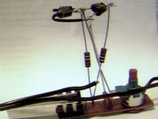
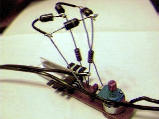
One more entirely gratuitous view.