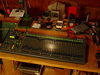
Power upgrade for Leprecon 1536 desk
[Each image is a link to a larger version.]
The Washington Street Players had become sufficiently frustrated with their
lighting board flaking out on them that I offered to haul it home and give
it a real grounded power feed, since it had already been observed that the
ungrounded metal case was definitely a factor in causing problems.

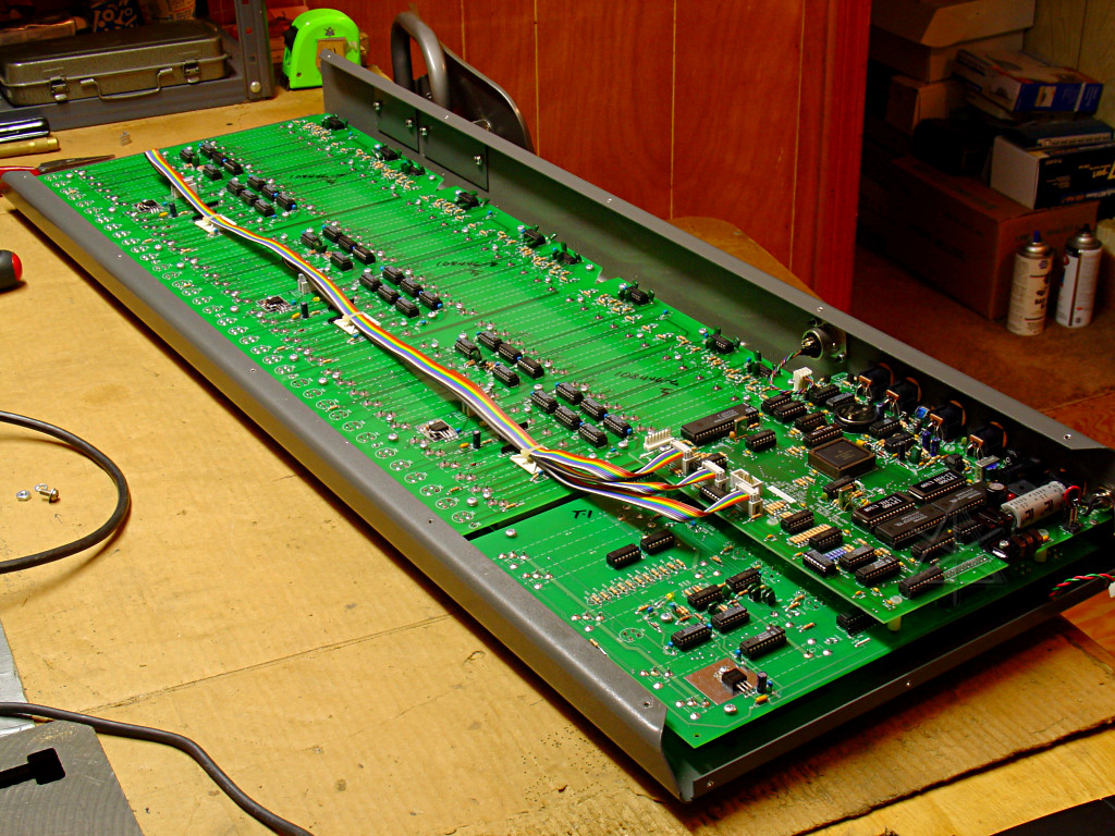
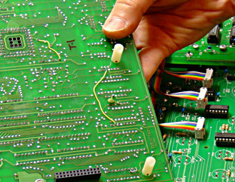
Sixteen sheet metal screws later, the bottom cover is off and we can make some
observations.
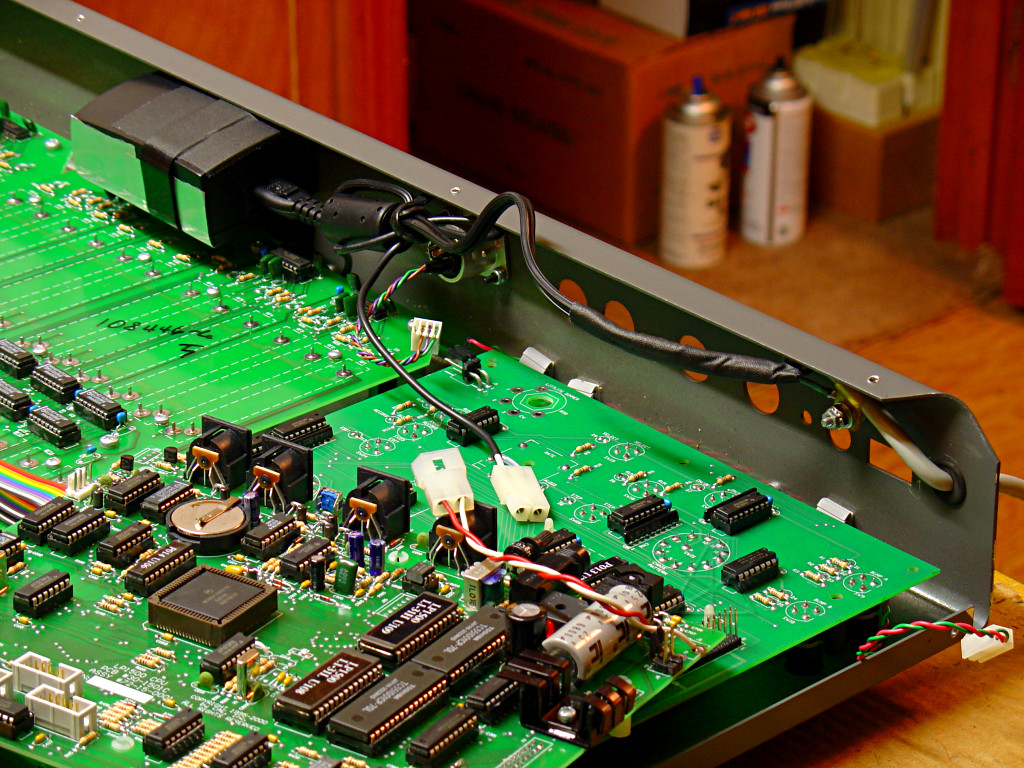
The main processor is a 68K variant. The processor board is the one that
looks like a daughtercard, and is also where power and I/O come in from the
rear panel.
The large boards farther away hold all the channel sliders, and each one is
a dual group of 12. This makes it easy to construct the 12, 24, 36, or 48
channel desks with the same parts.
Almost all the chips are socketed, facilitating easier repairs. 7805
regulators are sprinkled liberally around the unit to provide 5V power to
various parts, and it appears that that's the only voltage it uses internally.

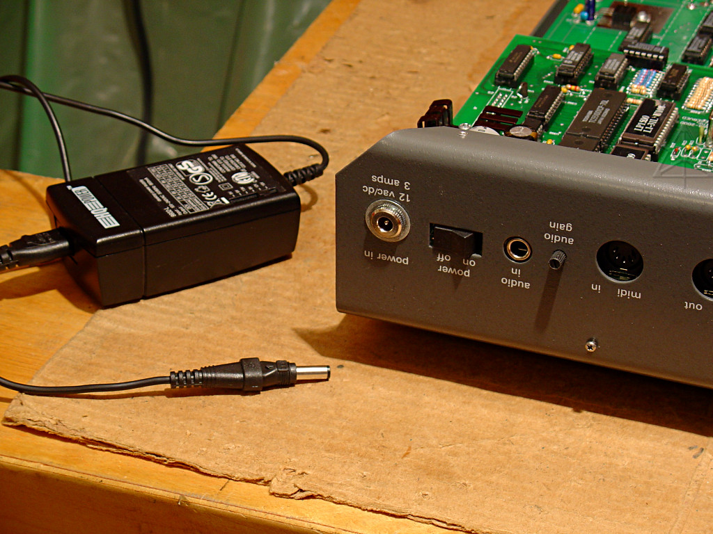
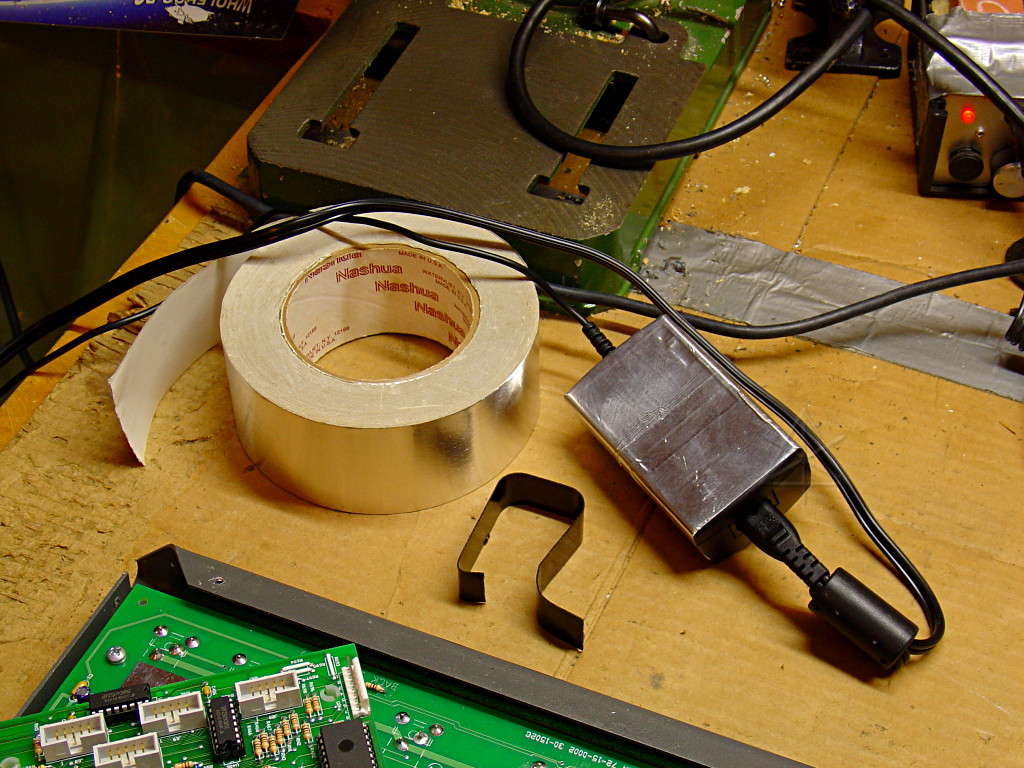
This is the flakey power supply and input jack in question.  The hole in the
concentric plug is too large to fit snugly, and of course the whole thing is
2-wire and ungrounded.  The original supply was apparently lost and this is
a universal multi-voltage replacement.  AC or DC power is acceptable since
the processor board's power section includes a bridge rectifier and filter
section of its own -- a simple 12V transformer technically would do, but after
a little testing I decided I'd just re-use the line-wart widget provided but
hardwire it inside the board.  The maximum 12V draw of the electronics tests
at about 750 mA, and the Littlelite can pull another 300-ish at full bright, so
clearly 3 amps aren't really needed.  The widget is good for 2, holds a solid
12V under all observed running conditions of the board, and will fit into some
empty air space near the back.  So it will do.
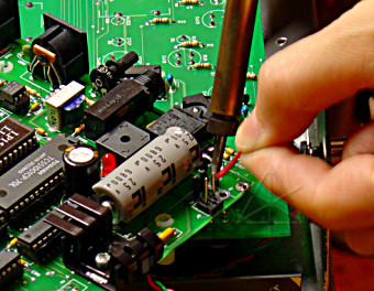
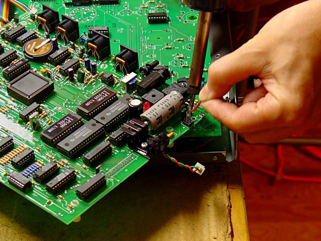
So the old power jack needs to be desoldered and taken out.
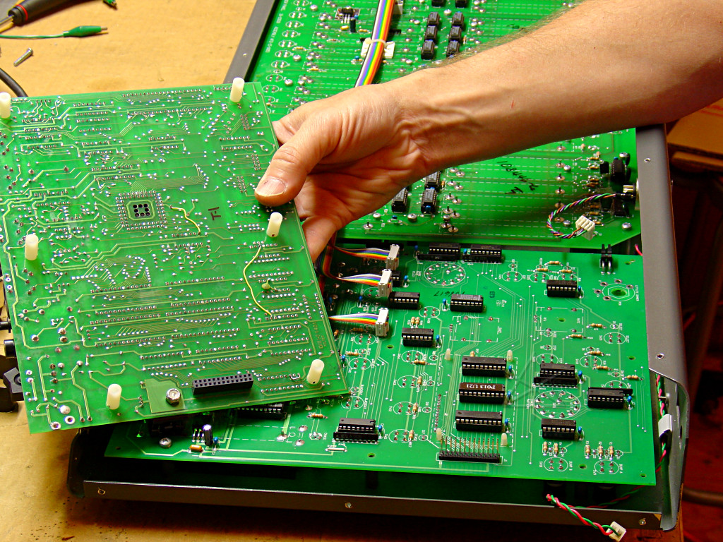
Free up the processor board and flip it over, and we find ... ECOs!

Early testing by holding the power wart close to the intended mounting area
presented no control interference problems -- being what it's a switching
supply and going to sit near some of the channel sliders, this was a mild
concern.  But just for paranoia's sake and possibly better heat dissipation,
we add a little self-adhesive shielding.  A clamp bracket is formed from steel
brick-strap.  Two holes are drilled through the back of the case -- one to
mount the wart clamp, and another for the grounding connection and power cord
strain relief.
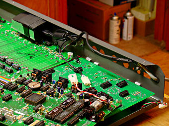
Wired up.  The new 3-wire power cord comes straight in through a grommet and
ground splits off to a lug tightened against bare metal around the clamp screw,
and the AC is spliced to the wart input.  The wart output gets a nice inline
Molex connector to facilitate future removal of the processor board without
getting out the soldering iron.
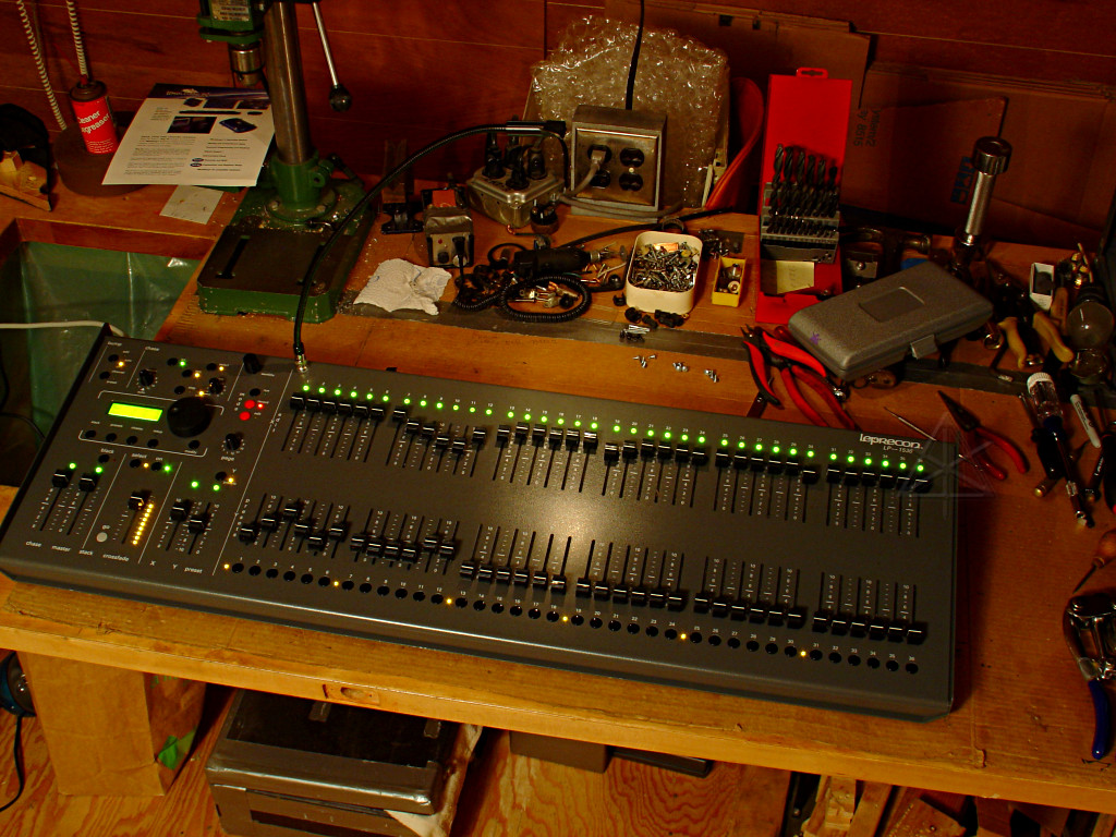
Functional test.  The largest power draw seems to happen when the board
lights up the most LEDs, which makes sense -- the baseline of the electronics
alone is more like 250 mA, so a "full load" test means getting all possible
LEDs to light up.  Channel mimics at full, a mostly-crossfaded cue, running
a chase, and in "record" mode so the lights down near the submasters blink.
And the worklight up at max.  Left it this way for a couple of hours, with no
significant heat developed above where the power supply now sits.  All this
had the processor pretty busy; response in the LCD display to channel slider
changes was a bit sluggish but no electrical interference or flakiness was
observed in sliders 7 - 12 nearest the wart.  And now the board can freely
be shoved around and bumped without crashing!
_H* 070910