Just lose the exterior OSB in favor of plywood, please ...
Another geek-fest ...
|
I decided that for a change this year I'd actually get myself to the
Building Energy
conference in early March, partially to see if I could hold my own
to meet and interact sensibly with some of the more serious
building-science nerds on their level. My head was stuffed with
all this new knowledge, a bit of practical experience, and some
early stats on winter energy use, so why not go do my own tiny
little part to promote the green-building industry in general. Of
course I also wanted to sit at the feet of the Great Masters if
they'd let me; what's any topical conference without at least a
little squeeing over luminaries in the field?
Overall the conference was pretty good and had many entertaining seminars *and* an extensive trade-show floor. It was definitely too much to try and take in all at once, especially when NESEA had organized it into something like eight concurrent tracks. I did get to meet some of the guys whose papers and case-studies and videos I had been devouring over the past year, and didn't hesitate to tell them that and thank them for the great online education. Joe Lstiburek unfortunately wasn't there, undoubtedly busy with some other gig, but I met a few of the other folks from BSI. Oh, and let's not forget to mention hangin' with Martin Holladay and trying to stump him with silly duct questions. But with all that information overload, I actually didn't learn that much that was truly new to me. Almost everything people were there to discuss is out on the net, and it was a nice affirmation that I'd absorbed a good quantity of it already. That's not to sound snooty -- there's just so much that the choir can preach to the choir and the next big challenge that the community is working on is bringing all this more to the mainstream. The fact that the IECC and derivative building codes are rapidly being updated to add many more efficiency requirements is one visible result, and it sure ain't over yet. |
... and a bit of backlash
|
I also spotted a couple of guys from the subcontracting group who did my
main retrofit, greeted them, and mentioned that I'd made a lot of progress
on my writeup by then. They got curious, and by the second conference day
they had read most of the parts that involved them and they were *not* at
all happy with me. While I had successfully expressed how the overall job
went together in a pretty awesome way, I also pulled no punches in noting
some of the downsides and that hit them pretty hard, to the point that
they tried to convince me to take the *entire thing* off the internet.
We managed to resolve this in a non-antagonistic fashion. Details of the discussion and process are here for those curious, especially those who may have read a revision prior to, say, early March 2013. |
More data from the field
|
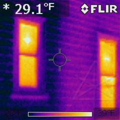
Armed with the IR imager, before we ran out of cold weather I went around to
visit said colleague and some other friends for some informal energy audits.
On this particular house the residents had recently redone the kitchen which
included better insulation in its part of the exterior wall. The difference
between that and the non-upgraded mostly-hollow wall was fairly profound,
but obviously the windows were a larger loss point.
Note the heat profile on these windows, too -- apparently most transmissive at center-glass. Newer but fairly generic units -- I don't recall if they were single or double pane but certainly didn't contain any exotic gas mix. |
|
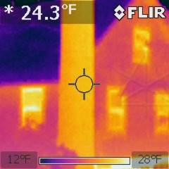
Back home, I was still trying to determine any contribution from the
Reflectix shades -- where the leftmost window here was left unshaded for
a while, and the rest had their barriers in place. Again, a slight
difference around the sashes, but the main thing to notice here is the
very different overall thermal profile of the Serious windows here versus
the ones on the friends' house.
Oddly, the tree seems warmer than the house but that might be that same low emissivity characteristic of the siding vs. that of oak bark. |
|
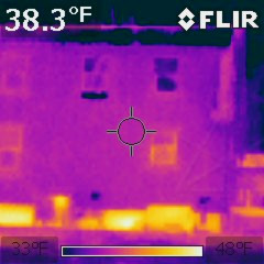
There was still my larger and more annoying loss issue to figure out, visible in a whole-house shot from the back in the daytime -- the basement wall, persistently glowing far more brightly in the IR spectrum than anything else. Clearly, the meager R-3 or R-4 of the old white styrofoam wasn't cutting it against winter chill outside. And the brightest spot along there, about center in the image, happens to be right where the top of the water heater is located inside. Funny, that. I considered if it might be worth wrapping a big fiberglass blankie around the piping on top... |
|
So I really wanted to do something about this. Some sort of additional
insulation was likely needed, and while outside the foundation wall is
the theoretically ideal place to put it there are real-world issues with
insects, frost, and excavation that make it rather impractical for an
existing wall. But I still had all this leftover two-inch polyiso that I
kept the builders from pitching into the dumpster, some of which was
already loosely puzzled into a layer over the slab and the rest of which
that people hadn't taken away was piled up out back. I didn't want
to just apply that for fear that an interior vapor-impermeable layer
would trap moisture and do bad things to the wall behind it. I thought
about using the 2" polyiso but stripping all the foil-face off first
to make it a little more permeable, which seemed like a lot of extra
work for a dubious theory. And then
at the conference, I had the "epitome conversation" with one of the
guys from Building Science.
Basements are tricky, and popular wisdom had come to be that since concrete in a foundation wall cannot dry to the outside because the soil is always at 100% humidity, it has to dry to the inside. In examining numerous research results and futher consideration, Dr. Joe [the industry's go-to guy for such wisdom] had recently reversed some of his thinking on this matter. Let's face it: concrete is fundamentally rocks, like all the other rocks along with the dirt that surrounds the foundation. Whether or not it's faced with dampproofing, those carefully structured rocks we set our buildings down on are going to basically stay moist. We work hard designing our envelopes to keep excess moisture on the outside, so why give those basement rocks any special consideration and continue a largely futile effort to dry something that's always being fed water from the other side? The conclusion was that as long as bulk water ingress isn't part of the picture, it's okay for concrete to be wet -- it likes to be damp, in fact, and entombing all of that behind an impermeable seal would be the right answer as long as said means of entombment did not include any moisture-sensitive materials. Which does *not* include the wood framing with fiberglass batts and paper-faced gypsum board that so many builders of "finished basements" have had backfire on them over the years and turn into instant mold farms. Closed-cell sprayfoam, directly-applied rigid foam with sealed joints, or combinations thereof had returned the most favorable results. It was already clear that despite being porous and thus quite vapor-permeable, the ancient styrofoam was holding back some pretty serious funkyness on the walls anyway. I had been going around patching up some of the missing areas and taping up its seams in an early halfhearted effort at air blocking, and sometimes when I removed a bit of the old stuff to replace an area with a more intact piece I got a pretty strong whiff of spores or mycotoxins or whatever the wall was throwing at me. While mold can't feed on the concrete itself there was something on the cinderblocks that clearly could support it, perhaps just accumulated dust, so I realized up front that trying to take the styrofoam *off* first would likely expose an existing mycological disaster to the rest of the house. No, the answer was to simply bury all that and add another well-sealed layer on the inside, letting the block wall be as moist as all the other rocks out there but not in a way that could condense interior air. Preventing evaporation at the block surface would likely stop any more efflorescence, too. |
Foam, foam, on the wall
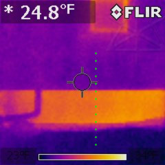
|
Maybe I was just kidding myself, or maybe I could actually see a *very* subtle gradient on the exterior around where the edge of my test patch was, somewhere around the dotted line. But with the internal webbed block structure and convective air columns comprising a broad thermal bridge to the inside, I really had no idea what to expect to see here. |
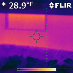
|
On the side wall it might have been a little sharper except that the edge of my patch also stopped at the edge of the window, so what I was seeing could have easily been thrown off by effects from the cutout or the window frame itself. |
| One possibility I'd discussed with my basement-wall mentor at the conference was that the *outside* soil could also be contributing warmth from its perpetual trying-to-stay-55-degrees deeper down, i.e. sending some amount of heat into the wall from below which would then emerge from the above-grade area. That aside, I knew the walls were fairly cold all the way down because of the air columns inside, and it was becoming clear that effectively insulating this was going to pretty much be an all-or-nothing effort to make any difference. But blocking the inbound humidity diffusion seemed like a worthwhile goal too. | |
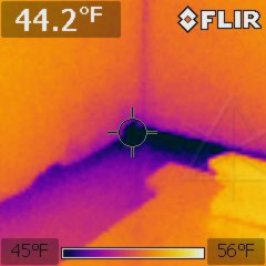
|
There was also the slab to think about, but connected to a steadier mid-fifties seasonal ground temperature underneath the house instead of ambient air it probably wouldn't leach nearly as much heat out of the premises. Especially if the basement air was allowed to stratify and be colder at the bottom. It was already clear that the walls were coupling to the edge of the slab via conduction or interior air convection or both, cooling the edge, but things were much more moderate toward the middle of the slab. As something of a compromise, I figured I'd include insulation a foot or so in on the slab itself and build up the wall from there. |
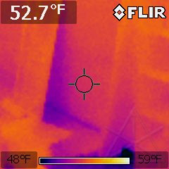
|
While slinging and stacking the many odd pieces of foam around I noticed an interesting effect: when I leaned a piece of the polyiso against the EPS-covered wall, a thermal "shadow" would form behind it. Remember that this is heat, not light, and it wouldn't appear instantly but rather took 20 or 30 seconds to develop. The "image" would take about the same time to disappear once the polyiso was moved away. My best guess is that some heat was radiating from the items inside the basement [including your humble author's corporeal being] and the floor structure above, helping to warm the inside surface of the styrofoam, and when that path was blocked the conduction into the colder wall would take over and chill the area down. Whether this theory was correct or not it was more evidence that the styrofoam was pretty wimpy insulation. |
|
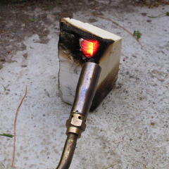
There's also all this talk of ignition barriers needed over various kinds of foam insulation on the interior -- intumescent paint, drywall, or whatever. Code calls for such things over materials that already have pretty low smoke and flame-spread ratings, and various tests I'd done showed most of the foam I was working with to be largely self-extinguishing. Since the foil-face polyiso would become my new interior surface, I did another torch-test on it. It took a fairly insistent flame to penetrate the foil, after which the foam burned a surprisingly small amount and quickly put itself out leaving a largely intact cellular structure that simply *would not burn* anymore. We're talking space-shuttle tiles here. |
|
Maybe it wasn't a full-on ASTM "corner test", but
I torched it bright-yellow-hot without seeing any further combustion and
concluded that the foil-face would be even safer than the styrofoam that
I already wasn't particularly worried about, without messing around with
any additional coatings for the moment. Moisture-sealing or not, there
was no effing way I was going to put up any *drywall* down here. In
researching what compatible intumescents were available at the time I had
an amusing conversation with the engineering guys at
TPR^2, whose
BlazeLok and Fireshell products weren't specifically geared or tested
for application to foil-face but they said they were definitely working on
the problem. And really, the foil also serves as a radiant barrier and I
could see no good reason to cover it and destroy that capability as my heat
issues in question seemed to have a lot to do with radiant transmission.
The local building inspector had already been through the basement a while back with all the ratty old white styrofoam in full view, and never said a word about it so for the moment I was likely off the hook about any of this. Maybe I'd worry about it if I went to sell the house. | |
|
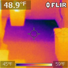
Under a recently-lifted larger piece of polyiso, the thermal profile of the slab floor pretty clearly showed the cold area taking kind of a diagonal across the corner, which makes perfect sense given that corners present more surface area to the cold. |
|
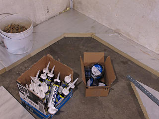
So I figured my "footing" on the slab should do the same at the corners, to
better follow where the cooler areas would lie. My footing width wasn't
necessarily a full foot wide everywhere, but I was using whatever long
pieces seemed to conveniently fit in.
In addition to coming home from HD with most of a "contractor pack" of Dynaflex caulk, I found a good source for rolls of the Weathermate tape to seam-seal the polyiso once it was up. I got the less expensive two-inch instead of the three-inch, as this assembly wouldn't be exposed to weather. |
|
As it turned out, the leftovers of polyiso and other random stuff I still
had kicking around was enough to bring my odd patchwork all the way
around three-and-some out of four basement walls -- much more than I
expected. It was quite the puzzle sometimes figuring out which pieces
to put together to minimize waste and cutting, but it worked out rather
neatly and stopped just short of "infrastructure row" where the
water-heater and HRV and laundry stuff is clustered. That was good
enough for the moment and I had several more general fixups in that
area to do anyway before getting more foam to complete the run.
Supermodels So now I was committed to having stopped whatever moisture and infiltration air path may have existed through the cinderblocks, which would likely help keep the basement drier in general. Some could still permeate the slab, but probably not nearly as much as the block and with the new overhangs at the roof and built-out walls, the dirt by the foundation was generally staying far drier than it ever had before so going forward there would be less water around the walls at all. The only remaining small concern was a drying path for the sill and beam-pockets, but everyone I talked to and showed my little diagram [below] agreed that the generous above-grade span of unfinished foundation wall would provide plenty of diffusion area. There are still plenty of uncertainties in the field where insulating basement walls is concerned, especially once a wall starts getting colder in the winter. The recent Report 1005 from Building Science gets into this around page 50, and concludes that "more information is needed". Well, I was probably well on the way to having a rough candidate data set.
Said diagram came from some playing around with GIMP in advance of the conference, so I'd have something to show people while asking my questions. I sort of followed the informal DER case-study conventions where existing structure is shown in light grey and new construction uses more indicative colors and fill patterns. Obviously I could never apply anything impermeable on the *outside* of those blocks to seal them, as that would channel any rising ground moisture straight up to the wooden parts and likely be their death knell. The firm butted contact between the sill piece and the joists and studs does provide a tenuous path for some sill moisture to escape toward the interior, but I wouldn't want to rely on that as the only means. And yes, that lowest piece of sheathing does have a big aluminum heatsink to the outdoors and is going to run colder than the rest -- that's one minor downside of this configuration, but the other side is mostly encapsulated by the sprayfoam and I didn't notice any condensation in that area during cold times. |

|
Late March brought a few warmer days and some first signs of spring: some
early shoots popping up through the decidedly frost-heaved soil
in the yard. That didn't stop me from trying to
squeeze in a few more heat-loss tests, as the nights were still fairly
cold. With the supply ducts now better insulated against radiant loss I
wanted to see if the toaster would perform any better, among other things.
I ran a few nights alternating between running on the heat pump alone and
the toaster alone and comparing energy used against
local degree-days,
and confirmed that the heat pump was delivering a COP of right around
3 at 32F ambient.
I also fiddled around with high fan vs. low fan, which didn't seem to make a whole lot of difference but it wasn't anything like a rigorous test. With the ducts rendered less lossy I thought that low fan might create less static pressure through the system and cause less air transfer between upstairs and basement, and possibly reduce the amount of warm air washing against the exterior walls opposite all the supply registers. Fine points, probably not relevant since rough calculation indicated that (CFM) * (dT) = a constant regardless of high or low fan anyway. |
|
|
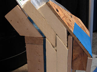
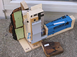
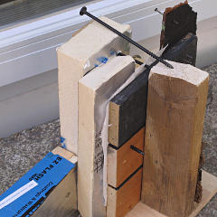
| Inspired by some of the mockups I'd seen at the conference and having noodled up some decent drawings of my own, I wanted to do my own wall-section model to show the old and new assemblies together. I had saved a few bits of the old material, the siding and tarpaper and ratty Kimsul insulation ... and had some appropriate-thickness boards to simulate the plank sheathing. Once a pseudo stud was attached to a suitable baseplate, the rest fell together pretty quickly including a way to show how the Headlok screws tie the strapping into the original framing through all the layers, how foam seams get staggered and taped up, and how the "buttons" temporarily hold the foam on and that it's common for those mid-field screws to poke through the sheathing. A couple of extra parts clarified window and door buck construction, and of course I had to toss in one of the cut-off rafter tails with its visible history of water issues, to help explain the benefits of the "chainsaw retrofit". | |
| I took this with me when I went out to visit a DER open-house out in Worcester, where it was well-received and I met up with a few more industry luminaries. One of them posted later about our discussions on heat pumps; the mention is fairly far down that page so search for "goodman" to find it. That particular retrofit was a largish three-family with three separate Mitsu outdoor units, all hung on the house on wall brackets about 4 feet off the ground. An interesting approach to a basement-bulkhead door there was to build sort of a small insulated "tunnel" off the exterior wall to hold a second door about two feet inboard of the foundation line, leaving the old ratty outside door in place. | |
|
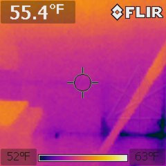
Some warmer days arrived rather suddenly, and with the daytime sun still fairly low it was hitting the foundation wall in back through the leafless trees and making a pretty clear thermal gradient up the still-exposed styrofoam on the inside. Okay, so exterior temperature changes were showing up on the inside. I already knew that would happen, just not exactly how much, but once the foam job was completed that was going to largely cease. |
Follow the money
|
Early to mid April saw the wrapup of heating season, and I went back over
my data-collection for a review of the overall energy needs. Glossing over
a lot of detail, the indoor meter showed 1963 kilowatt-hours used for HVAC
alone, e.g. pretty much the moral equivalent of how many gallons of oil
I would have burnt with the old furnace. Averaging the on and off peak
electrical rates to 11.3 cents per kwh that worked out to $222 spent on
heating from November to April, over 5041 heating degree-days. It was
probably even less than that after programming the system to revert to a
low setback over the peak metering period and let the house just flywheel
across it until 7pm, but I'm ignoring specifics on that for this year.
Assuming a *very* modest average COP of 2.5 at the heat pump, it took on the order of 16.75 million BTUs [plus whatever came from plug and people loads] to keep the place at a nominal 65F most of the time. Burning oil to make that in the old furnace, based on my efficiency figures, would have consumed a *minimum* of 186 gallons or about $650 at the cheapest per-gallon rate I saw advertised that winter. All this is very rough and ignores the fact that extra electricity was consumed over times I was test-running on the three-kilowatt "toaster" -- but that probably balances my occasional use of the bedroom space-heater with the main system set way back and not running. Nonetheless, I could already see significant heating savings, not to mention the priceless peace of mind not worrying anymore about flakey old combustion appliances wheezing away in the basement. And keeping the entire pre-retrofit house that warm with oil would have cost *far* more, even with the storm windows and trailer-park plastic over the insides. Did you catch that? $428 or better calculated savings over the first heating season from the heat pump alone. Better, the all-told combination of heat pump and retrofit had likely reduced the annual heating energy *cost* by an order of magnitude from the pre-retrofit state of things. In the case of this and indeed most existing-building retrofits, it's unfortunately still not worth talking about "payback time" which is on the order of multiple decades, but all of these lessons learned plowed into *new* construction can mean huge energy reductions for relatively little incremental cost. Another less-tangible but monster benefit was the fact that this had been the first winter in a *long* time where I didn't get knocked down at least once during it by some sort of two-day flu/fever bug. I attribute that directly to radically improved interior air quality. The additional energy factors were numerous and made exact calculations far more difficult, but could be somewhat ballparked from the difference between the main meter and the HVAC meter. In this case that's about 6.8 million more BTUs worth of input, but consider that some of that heat energy went right back outside the envelope again carried by things like drain water and a few times I used the block heater on the car. All told the 23-ish million total BTUs I can account for over the HDD65 history for the period shows about 190 BTU / hour / degree-F total envelope loss, in comparison to the 300 I'd come up with for the old envelope. But ... only a one-third loss reduction from all that retrofit work?? That couldn't possibly be right. Two major unknowns were likely throwing things off. One was the basement loss, a huge indeterminate nonlinearity which would be at least partially mitigated before the next winter. The other was that likelihood, again, that I'd underestimated the total furnace output. An old service card I found from the last time "professional" hands had touched it showed test results at 73% efficiency with the big ol' "wall of flame" nozzle still in it, higher than I was willing to allow it given what I was able to measure but which would have put its production at around 75,000 btu/hr in that configuration. I also never considered that the warmed chimney might be radiating a bit more coziness into the structure, even if some of that was escaping up the chase into the cold attic. Oh well, there was no way to re-measure the old loss figure now even though I went back through some of the old data and tried to look up official degree-day history from then and "fit the points to the curve" -- that kept landing in the neighborhood of the low to mid 300s anyway. And with the old thermal boundary pretty much at the second-floor ceiling instead of the roofline, the old setup had a slightly smaller total surface area for net R-value figuring. So clearly more study was in order, but at least additional enclosure improvements were under way and I had a better idea about how and where to collect data. As imprecise as some of it could be, I was totally loving the engineering aspects of all this. |
Glaciers push things
|
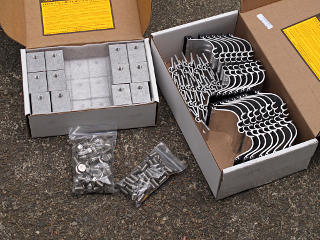
Researching this was fairly easy; the ATAS web site points right over to
the S-5! site as the
system they most recommend for their standing-seam roofing. I had also
visited S-5!'s booth at Building Energy. Obviously I wanted a non-penetrating
type of attachment, and the seam clamps that go with their "ColorGard"
system looked perfect. Loading math given the roof angle, panel width, and
assuming a couple of feet of heavy wet snow at 20 pcf showed about 250
pounds maximum longitudinal load, well within the rating of the "S-5-U"
type clamps if I installed one on every seam. I already knew the roof
structure was good for heavy loads in the vertical,
from a couple of winters prior when I was up there shoveling like everybody
else in the area -- and if anything, the whole structure was stronger now.
Within a couple of weeks I obtained a nice kit with all the necessary parts. |
|
The only mild concern was the panel attachment itself at the top, and for
that I had to go back and look at some of my installation pictures. The
panel edge clips are designed to slide and can't be counted as "fixity".
Each panel got tagged in with one screw as they went on, and then each Z-bar
had two more holding it down for a total of at least three per panel. While
the S-5 tech-support folks I talked to implied that they'd normally expect
more like five, they were thinking wider panels and more like every other rib
or so supporting the snow-guard system. Clamping every panel would distribute
the load across all of those screws, and besides, they were all into plywood
and not OSB so that was a big plus on holding strength.
For what it's worth, adhesive-based retention systems weren't even on the table for my consideration. Too many detachment failure stories. | |
|
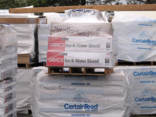
I had ordered through Beacon Sales a couple of towns away and went over to pick up the parts a few days later, and while in their yard happened to notice a pile of stuff allocated for another retrofit that my GC's subcontractor was doing. That was pretty amusing to find. Clearly, regardless of whatever I might have ever said about those guys they had plenty of work keeping them busy. |
Heading for summer
|
|
|
A while later came a couple of *really* warm days with sun beating down
on the roof, and I was curious how the new structure was handling that.
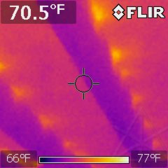
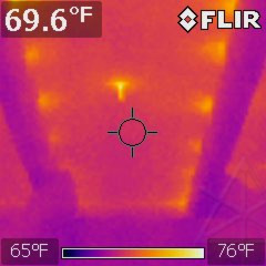
The IR image was really amusing. Each long screw from the outer plywood
into the rafters was clearly forming a little thermal bridge all the way
in and warming
spots in the wood, looking sort of like a theatre marquee. The exposed
ends of the mid-field button screws, particularly from the outer layer,
were quite warm to the touch.
But even with metal conduction the bridging is all quite small in terms of area, and wasn't actually bringing a lot of heat into the attic. And it was already clear that the roof metal, with its finish SRI of 51 or so, was bouncing a healthy share of the heat impinging on it -- while up top I found that with full sun on the panels the metal quickly got almost too hot to touch, but cooled rapidly whenever a cloud came along. That, similar to what the siding does, does lead to a certain amount of creaking and groaning from expansion on those in-and-out partly cloudy days. | |
|
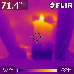
The stink-pipe showed a healthy thermal gradient, but nicely contained in the PVC section. That would extend much farther down if the whole thing was still black cast iron. |
A far better ODU screen
|
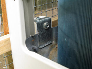
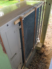
Here's how the clips go on, and the screen frame simply screws into the other side of the Azek block. All zinc-plated screws, for best compatibility with galvanized. |
|
The frame was constructed from various old trim scraps, in minimal
thickness to avoid interfering with airflow and all urethaned up for
weather-resistance.
I was pretty happy with the result, even if the piece of half-inch mesh
was kind of ratty and bent -- it was free from some friends already in
a mostly perfect size, I didn't have to go buy a roll and then only be
able to use a small part of it. It sits over an inch away from the
coil, with the intention that it would totally prevent that blowing-snow
freeze-up problem.
It was now a little more like that shroud structure I'd spotted with the iced-up pipes at the local show hall a year ago, than the practically useless open plastic grille that came with this thing. |
Air box access
|
One thing that the HVAC installer had never taken into account was how
to access the underside of the indoor A-coil for cleaning and inspection.
That's the side that will get dirty despite the filter, of course, and may
very well need a brushing-down once in a while at minimum!
While I could sort of see it from the filter box with a mirror and a light
I couldn't actually reach it, and what I really wanted was an access
opening in the box underneath the whole air-handler assembly.
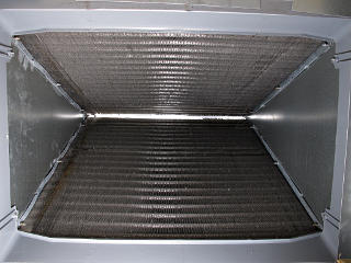
The problem was that the wood structure inside the air-box would interfere with a hole cut into either of the two surfaces I had available, limiting the maximum working opening. |
|
Now I could finally see and reach the whole underside of the coil. It
had even gotten warm enough to test-run the cooling, and watch it load
up with water which is what's going on here. The plastic drain pan
has a fairly generous height, and while the coil fins fit fairly tightly
down into it I can watch for bottom-coil corrosion here and maybe even
vacuum out a little additional water at the end of cooling season. Later
on I discovered that because the whole tray with the coil in it gets
cold, a little condensation also forms on the *bottom* of the tray
and drips off into the bottom of the air box. It's not a lot, but despite
Martin's misgivings
about pressure-treated lumber in an air plenum I'm glad it's in there.
Routine activities in here would be way more palatable that grubbing around in that sooty old furnace firebox, for sure. |
| At this point I also removed the "toaster" heater entirely from the top of the unit and set it aside, so it wouldn't get washed with the high-humidity air coming off this all summer. While evaporator coils remove water, the exit air's resulting 100% relative humidity doesn't really drop until it circulates back into the space and warms up, which by the time it's through the blower and distribution box hasn't really happened yet. Why risk faster corrosion of the heating element when it's trivial to just take it out when I don't need it? And my COP-1 watt-hour measurements aside, I arguably don't even need it back in for winters unless the heat pump system craps out or it gets *soopah-wikkid* cold outside. | |
_H* 130706