House energy retrofit project 06

With the outdoor and indoor units mostly installed, it was time to tackle the ventilation components. The "V" part of HVAC, it's especially important in airtight buildings. Human activities generate CO2 and humidity and odors and other organic yuck at a surprisingly fast rate, and replacing that with a supply of fresh outdoor air is always needed. [Except around LA, where you only get to replace human yuck with vehicle yuck.]
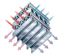
In old buildings, overall air infiltration and leakage traditionally took care of that. In the seventies when everyone got all excited about saving energy and afterward when better materials and construction techniques led to tighter houses, many people learned about ventilation needs the hard way as they kept battling headaches and scrubbing mold off their walls. The modern approach is extra equipment to supply controlled ventilation and replace stale interior air with fresh from the outdoors, except that nobody wants to push air they just spent money heating out of the house in the dead of winter. The energy-efficient answer is to exchange air through a heat recovery ventilator [HRV] that passes the two air streams near each other, without mixing them, across an aluminum radiator core assembly that thermally tempers the incoming air using energy from or to the outbound stream. Typical transfer efficiency is between 65 and 80 percent, and some of the true counterflow-core European units that we can't get in the US yet are up around 95 percent. At the fairly low volumes needed for adequate air exchange even the lower-performace units can let a building "breathe" well but retain significant valuable heat in the process.
An ERV or energy-recovery ventilator that could also transfer humidity was briefly considered, but with far less fiddly maintenance and in a mostly-heating climate region the plain ol' HRV was the right choice. I wasn't too worried about humid air, as long as it could get processed, e.g. dried, as soon as it reached the main air handler running in cooling mode.

    Veni, vidi, venti

The Synergy guys had originally planned on supplying an HRV to go with the overall retrofit and had specified a fairly small and simple one, but it didn't have the CFM capacity I anticipated needing at times and wasn't nearly as configurable. Since all the HVAC was going to get done well before the real retrofit started, back in the planning stages I had floated the idea of having the HVAC guy do the HRV piece too and they thought that would be fine. I didn't want to step on any toes as far as who might be subcontracting for who, but I had a pretty good concept of what I wanted and how to have it well-integrated into the rest of the new system and they let me run with that.

So then my HVAC installer and I went unproductively round and round with what specific unit I should get, as he said he'd tell me what his supplier had available but never got around to it. I got on the net and went shopping, reading comparison articles and owner experiences at the forum sites, finding horror stories like the one about cheap Fasco motors burning up inside Venmar-branded units, and basically kept researching different brands and features and other peoples' experiences until I figured out what would work best. I finally settled on the Fantech VHR1405R (pdf) with the defrost-cycle feature and fancier interval-timer wall controller, and asked that the supplier just bloody order that and be done with it. With a firm decision in mind we also then knew what duct sizes were needed to adapt to it.

A ventilation system design generally wants to pull air from near typical sources of "bad air" -- kitchens, bathrooms, basements. And my concept included adding the attic to that as it would also help circulate air through the entire second floor. I had a head start on some of this by intending to use the chimney path as one of the pickups, and the fact that the ventilation system itself would be in the basement. A new duct would be needed for the first floor, and I decided the easiest way would be to run a small line up the basement stairwell and punch it through the door rather than mess with trying to open up interior walls. So I had three vent collection routes in mind, all fairly easy to implement, and already had a place to mount a duct at the top of the basement door.
[Click any image for a larger version.]
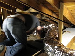
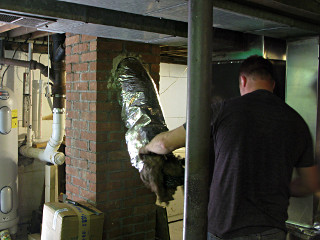
Trying to stuff flex duct down old flue We took a box of 6" insulated flex up to the attic, whose outer sheath diameter is more like 10 inches, and he tried to start one end down the old 7 x 11 inch chimney flue pipe. Because of surface roughness and various irregularities on the way down, the insulation compressed and the whole thing hopelessly jammed up within a few feet. Realizing that this needed to be pulled rather than pushed, I handed him a piece of rope to drop down the hole to where his helper was waiting in the basement. The end of the duct simply got tied to that and the guy downstairs started gently pulling as more of it was fed in from above, and that did the feedthrough trick in short order.

Flex received at bottom This turned out to be my free final chimney-cleaning, as soot rained down on the poor helper and the end of the duct finally emerged from the hole completely covered in black. But the nice result was that since the fiberglass packing made the outer duct sheath create so much friction against the flue pipe, the whole length simply held itself in place without any need for retainers or straps. So by using the oversize and very squishy insulated duct, that concern was already dealt with. The inner 6" spring-reinforced core was fine, fully open and pretty smooth and straight all the way down.

At this point well after heating season the chimney flue had been fairly well ventilated and smelled only very mildly of leftover combustion products, and only from right next to it. It has since faded almost completely, and was never discernible anywhere else in the house.


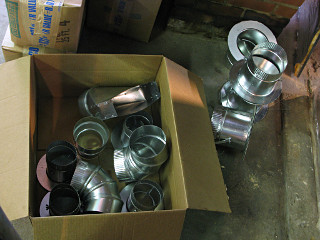
Duct fittings While the six-inch duct with its padding turned out to be just the right solution for the chimney shot, the installer was assuming that everything else was going to be 6" including the basement-stairs shot. That was incorrect per my conceptual design. We now had a pile of fittings on hand, but he hadn't brought enough 4" parts to put the rest of the interior collection pickups together. At least we could start getting the main HRV interface built.

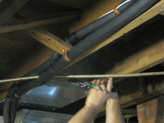
Cutting into HRV return duct A new connection was cut into that first bit of joist-pan he'd fixed up on the first day. This would bring HRV-tempered fresh air into the main air handler return side, pre-filter.

Yeah, they ran the lineset on either side of the stove cable and joist brace.


At this point the installer had to actually stop and listen to me lay out my ventilation design in detail, as hitherto he had only a vague idea. I had three collection points around the house clearly in mind, one of which was the basement-stairwell hack which given the somewhat confined space definitely needed to be a 4 inch run with a small offset duct boot. I showed him what I meant right out of a Hart & Cooley catalog. The six-inch shot from the attic was okay since it was a longer run and the remaining one didn't need to be anything special other than a 4" takeoff easily extendable with generic dryer hose and I'd figure out what to do with it later. In other words, various separate stale-air inputs combining into a common feed to the HRV exhaust stream, like we'd even talked about three months ago. *Now* he understood what needed to be built.

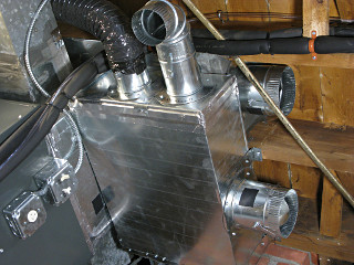
HRV stale-air combiner box The result looks like something out of a battleship engine room -- a little oversize but functional, and has adjustable dampers on every port to tailor flow as I like. The two large open duct takeoffs are to and from the HRV and their dampers allow experimentation with seasonal pressure balancing. The various bits of black gaff tape stuck on are to allow duct temperature measurement with the IR gun, as shiny metal's emissivity tends to confuse it.

The few leaks present in this rig absolutely don't matter, as one leg is open to the basement anyways. The nicest aspect is that it all involved absolutely minimal extra duct runs through the house and no need to open up walls..


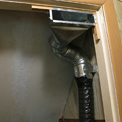
Stairway HRV duct, as built The next day the stairway pickup finally got put together, after he could fetch the smaller parts from the supplier that morning. He couldn't actually find a 4 inch register boot and wound up getting a 5" and adapting it down after the elbows, but it all fit okay and attached very nicely to the nailer strips I'd already provided right where I expected this to sit.

The duct hose is black because it's just the inner core from cut-apart insulated flex, as he hadn't actually brought any uninsulated 4". He was going to make this an insulated run until I intervened -- *none* of the interior HRV runs needed to be insulated, especially on the exhaust-path, as it's all interior air anyway.


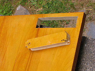
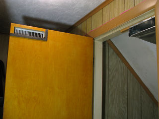
Basement door cutout I finished this piece up a little later, and here's how it worked out: The basement door got a corresponding hole cut through it, which I couldn't measure for until the duct boot was actually in place. It's a cheezy hollow-core door, but that doesn't matter as another bit of foam could just be stuffed in to fill under the slot. I saw where I would run into solid edge wood or air while cutting from a couple of exploratory holes I'd made in the door a while before, and knew its rim structure would still be intact around the slot. The rest was a fairly quick bit of saber-saw work.

Basement door duct rig done With the addition of a narrow 2 x 10 "toe kick" type grille on one side and two bits of weatherstrip foam on the other, it mates up with the duct and doorframe perfectly when closed. This is right near the bathroom and kitchen and reasonably far from any of the main system's supply or return registers, which is the perfect placement to grab from the typical stale-air sources in a home and carry that right into to the HRV's exhaust stream.

I also added another bend to the bottom boot flange to get rid of the sharp edge sticking down. I can walk down the stairs under this with plenty of headroom, and a taller person wouldn't really need to worry either. The whole rig can look a little ugly because c'mon, it's heading into the unfinished *basement* and nobody really expects things to be pretty down there.


    Meter move, and other fun

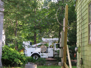
Power company arrives to deal with drop reattachment All hell broke loose the next morning, as the electricians arrived to wire up the HVAC stuff *and* the power company showed up to move the street drop from the house to the temporary pole. The latter didn't take very long, as the existing drop point was shifted over all of about two feet and could easily reach the cleat atop the post with a small messenger-cable extension.


My electrician had a couple of minor horror stories about the power-company linemen and their administrative structure, which had likely given me a distorted view of their attitudes toward customers and other workers in the field. So when one of the wire guys made some wisecrack seeming to object to the notion of me photographing the work, I thought "okay, where the F do you get off telling me what I can or can't photograph on *my own house project*". It actually led to a major misunderstanding, primarily on my part, about who these guys are and what they do. Let's remember that they *are* the ones out there in the middle of howling ice storms grabbing 13.6 kilovolts in their hands to put fallen wires back up on the poles, and they don't even get hazard-pay levels of compensation for it.

So where a previous version of this page had devolved into an excessively broad-brush rant about bureaucrats and unions and entitlement and the uncontrollable ubiquity of pictures on the internet, it turned out to be completely inappropriate and wrong and that I owed these fellas a huge apology for that. Unfortunately it wasn't until after several people had read the thing that I had the discussion that straightened the situation out and gave me the right perspective. Sure, it's true that some union situations have fostered a sense of elitism and have seen their share of abuses -- the auto industry comes to mind, including Toyota's prominent success and worker satisfaction as a strictly *non*-union company above the domestic ones that are. It's a fine line to tread, and everybody's got their own opinions. But with my small indie municipal power company they're not even IBEW, it turns out, and in that context their union is still serving the original intention of protecting workers' interests while they're out there helping people every day.

As it happened that morning the data card on my camera was full and I didn't realize it at the time, so my attempts to sneak a shot or two from chest level didn't even succeed so the one guy who was being a little sour that morning got his wish anyway.


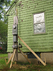
Power drop moved to temp pole The drop got moved to the pole, with the carrier cable extended a bit with a "finger trap" coupler. They were done with the reconnect and out of there in all of about 15 minutes, not even enough time to drain the UPSes keeping some things alive inside. You can't really see it in this pic but can in some later ones -- the messenger was run through the little eye on top and then simply twisted around itself a couple of times to finish, not even clamped down, but that was apparently secure enough to hold it against the pull from the street. Whatever -- I had power again, and work on the important stuff could continue.

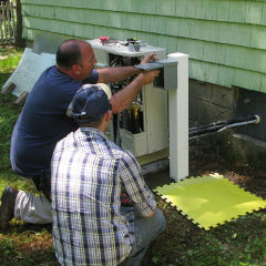
Wiring the HVAC disconnect The hutch I would eventually build over the outdoor unit wasn't about to happen yet, so the electrician stuck the disconnect on the easiest thing to put in -- a cheap vinyl fencepost from the Despot. Even though this was totally ghetto and flimsy, it apparently meets code so we went with it for the moment. And it put the disconnect high enough above the snow line to keep the inspector happy.

This crock would eventually get fixed, as would several other little details about the electrical work -- all of which gets detailed later.


My inspection of the day's work continued with another look inside the condenser unit, which they hadn't even closed up after wiring power to it. We weren't ready to fire it up yet anyway, as getting it commissioned needed the HVAC guy back with various tools first. But the new wiring inside it seemed a little sloppy, pulled really tight and lacking nice service loops or working slack, and then I happened to notice a little silvery shiny thing down in the works that I hadn't seen before. It was a small bulb connected to one of the refrigerant pipes that took me a moment to identify, and then only because of what was sitting next to it and what I thought I remembered seeing there before. "Hmm, this definitely ain't right", I thought.

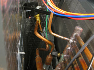
EXV stepper coil knocked off valve

The kid who wired power into the unit had apparently knocked the stepping coil right off the expansion valve while pulling wires through right next to it. Not like it's really firmly attached, as it just clips to the right-angle pipe to the valve, so this seemed like an honest mistake he probably didn't even realize had been made. But I had observed that he was a bit more rough and cavalier with things than I would have liked, and he really should have spotted this and/or been more careful running power.

It was interesting to see that the electronic expansion valves are basically built like a generic stepper motor. Compare how the inside of this coil looks to the one I had apart while studying voltage boost theory in regenerative braking.


Naturally this would have made life pretty interesting for the HVAC guy when he went to start up this unit, if it couldn't open its expansion valve at all. But these new systems give pretty good diagnostics, and probably would have produced a very specific error code like "E9" which would guide us to the right area. Rather than go through that exercise, though, I simply dropped the coil back onto the valve actuator after squeezing the clip a little tighter so it might grab the pipe better.

The wiring still seemed pulled too tight, though, and made me wonder if there had been any slack left inside the disconnect box I could shift through and perhaps alleviate this situation. Opening the disconnect involved all of one screw, so I took a look ...


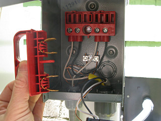
Disconnect miswired for dead short ... and this is what I found. Look carefully at where the black and white wires from the yellow Romex sheath -- the outdoor unit feed -- terminate, and then look at how the disconnect handle would try to complete a circuit to the unit when inserted into the slots.

Besides whacking my expansion valve all to hell, Mr. Sloppy had wired me a dead short, probably by being in too much of a hurry to read which screws are "line" and "load" in this particular box. Another honest mistake? Maybe not, maybe he just wanted to be in and outa here as fast as possible.


The result of this chain of coincidental observations was emailing that picture off to the head electrician, who was absolutely *ripshit* that one of his guys managed to do this and was falling all over himself apologizing back to me. Good thing I had discovered it before power was ever actually applied, as there would have been some entertaining fireworks not to mention a distinct possibility of "arc flash injury". I assured him that nobody had to come back that afternoon and that I'd just fix the wiring myself. Our relationship had already become both friendly and technical enough that he trusted me to do that.

In the heat of the moment both of us figured that kid was done as an employee, but the electrician is a really nice guy and after a strong admonishment he decided to keep the kid on, just barely, under strict probation to straighten up and work more carefully.

The answer to the original question was that there *wasn't* appreciable slack available in the disconnect box, so I figured I'd just run a new piece of romex later and keep its sheath intact most of the way up to the connection block. But not now, I didn't want to make extensive changes before they were completely done with this.


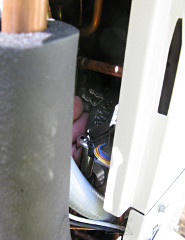
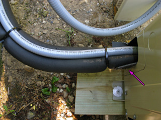
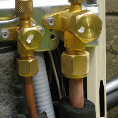
Padding lineset away from metal edge After getting the electrics nominally straightened out, a closer look at where the refrigeration lineset came into the back of the unit showed the vapor line pressing hard against the metal edge of the cabinet, hard enough to cut through the insulation. This could eventually cause all kinds of trouble from vibration and/or dissimilar metal contact in a frequently wet area. I couldn't really bend the pipe enough to move it away, so wound up shifting the entire unit over about half an inch on the stone bed to relieve the stress a little and inserted a hard rubber pad in against the cabinet edge.

The rest of the hole got temporarily stuffed with a wad of fiberglass to theoretically keep critters out, and later I stuck on a little rain hood over the whole area fashioned out of aluminum tape. Normally such fixups are never even thought of on units like this, but then you have to wonder what people think when we hear the common stories about corrosion problems or whole families of mice moving into these things.


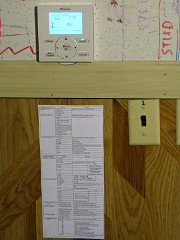
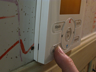
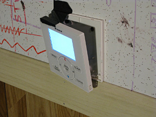
HVAC controller mounted, with documentation With power now connected to all this gear I could start playing with it a little. I couldn't run the outdoor unit's compressor yet but could at least power it and watch it boot, and at play with fan mode on the air handler and look at some of the settings and diagnostic stuff available from the controller. That's the new word for "thermostat", but this is a full-blown piece of electronics using a simple two-wire data-over-power link to the air handler. Gone is the old-school multiple wire 'stat hookup with R, C, W, W2, G, etc -- this sends all that functionality and then some over one wire pair. The installer had even reused my old thermostat wire from the oil burner to hook this up, since it was already there run through the wall to downstairs.

In anticipation of obtaining lots of interesting data from the system, I had already printed up one of the sensor charts from the "engineering data" manual and taped it to the wall under the controller. The installer was rather amused when he saw that.


Thermostat mounted badly I couldn't reliably get the fan-speed button to work, and it turned out that the reason was that the installer hadn't routed the 'stat wire right and the resulting lump was preventing the controller panel from seating all the way onto its mounting bracket. It was therefore pushing on the back of the circuit board right behind the button in question. This was easy to fix, and helped by clipping out a superfluous plastic rib inside near the communication terminals.

Trying to cool off controller thermistor By comparison with my various other references, the controller was reading a room temperature about 3F too high. Shooting the unit with the IR gun showed that parts of it were actually a bit warm, as its electronics must dissipate a watt or two simply to operate, so I figured the thing was actually falsely heating its own room-temp thermistor. In an attempt to verify this I unclipped it from the bracket and just hung it away from the wall for a while so any excess heat could more easily escape and waited to see if it would equalize.

That wasn't the right answer, though. The room thermistor is behind the slots in the lower right corner and far enough below the warm spots on the circuit board up near the display that it doesn't appreciably self-heat after all. The right answer came later from Daikin's applications-engineering department, a field setting that allows configuring a thermistor offset to compensate for inaccurate reading. I plunked in "1C-A-04" to configure a -2.7F offset and then it was in dead-nuts agreement with everything else.

This particular system depends entirely on the controller thermistor to sense room temp, where some systems depend more on a sensor in the return-air stream to determine demand. The latter scenario would NOT have worked well for two reasons: it requires the blower to always be running, which isn't necessarily the case, and the fact that the HRV would be dumping air at a different temperature into the return would totally confuse it about the actual temp in the house. So having this one accurate was fairly important.

In further playing with the controller I found that many of the data parameters supposedly available under the "maintenance menu", particularly for the outdoor unit, were simply not present. I could see how many steps the indoor expansion valve had opened, but the outdoor expansion valve kept coming up as "--" as did other things of interest like compressor RPM, fan step, and outdoor ambient temperature. After reading the lovely theory in the manuals that all of this data would be readily available, it was *profoundly* annoying to not have it. Daikin's application-engineering group couldn't come up with any better answer than "that's just the way it works" and blamed Japan for the omissions. Like with so many other product deficiencies of this sort, as soon as you cross the pond there's no recourse or remediation to be had.

Hmmph.

At any rate, I was pleased to discover that the blower is *whisper* quiet by comparison to the old furnace, even on high fan. With its fairly large wheel radius, it doesn't have to run very fast to move a generous amount of air -- I could barely hear it upstairs, especially through my freshly reworked registers, but there was all this *breeze* coming out of them.


    Commissioning, sorta

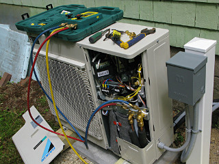
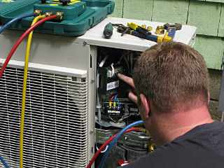
Set up to vacuum down system Finally the day arrived to start up the heat-pump system, which I figured would be a fairly long and involved process given what the Daikin manuals all said about the procedure. The installer arrived with his electronic pressure gauge kit and hooked up. His vacuum pump is on the ground out of the picture and connected to the yellow hose; a typical two-stage unit used by HVAC service techs everywhere. He fired it up to pull the air out of the lineset and indoor coil, and we left it going and went inside to noodle around with some more of the HRV ductwork for a while.

Here's where things got more interesting: he vacuumed the system for less than half an hour, and didn't even have a "micron gauge" hooked up -- a much more sensitive and accurate vacuum gauge than just relying on the negative region on a typical gauge set. His electronic gauge had a sort of halfass vacuum indicator built in, but it wasn't really accurate and somewhere around its "-13" PSIG reading was certainly not the depth of vacuum we wanted. Well, at least what *I* wanted after watching several videos where they're pulling these things to 300 or even 200 microns.


He didn't think anything of this, and completely skipped the other major step of doing a real pressure-holding test of the lineset in favor of just cracking the service valves and letting the factory charge out of the condenser into the rest of the system. I questioned this pretty seriously, and he kept saying it was all fine and didn't need all that stuff the manual listed. All he wanted to do was get the unit running, and that turned into a bit of a travesty.
Trying to figure out self-test mode It soon became clear that he had never started up one of these newer units, and didn't understand how to put it through its *mandatory* first-time self-test before it would actually run normally. This wasn't a simple "ask for max cooling" deal; his Daikin training was just out of date enough that he didn't know what to do at this point. *I* knew the theory on what to do but didn't want to tell him his job; I played along and we both sat there reading the install manual and the paper inside the unit cover and finally found which button to poke and for how long, and eventually the thing started making some noises and going through its diagnostic routine.

Look, we're beer-can cold! The head electrician happened to arrive just in the middle of all this, and he and the HVAC guy stood around shooting the breeze while my attention was *riveted* on the unit as it went through its various test stages. So imagine this: these two contractors are gabbing away about politics, past job adventures, supply houses, whatever ... and I'm crouched down in front of this unit listening to every little nuance of the noises it's making and hugging the fuzzy blanket wrapped around the compressor so I can tell how fast it's running and saying "hey look, guys, this is *fascinating*!"

Whether the professionals in the room cared or not, in a little while we were "beer can cold" with frost on the vapor line and the self-test finished itself up without throwing any errors. The system was finally ready to operate for real.


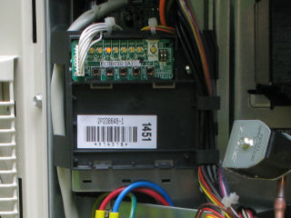
LEDs for normal operation This is what the little LED panel shows during normal operation, with just "IND" lit steady showing that it's in standalone operation. If it was ganged up with additional outdoor units, like can be done with Daikin's larger commercial systems, it would show either "master" or "slave". The condensers can be connected together through simple tees in the refrigerant piping and a daisy-chained data line -- pretty slick for easily expanding capacity when needed.

With system operation stopped and quiescent but still powered up, I could hear a characteristic soft high-pitch whine of the inverter running. It was a little mysterious why that would be when the compressor wasn't spinning but after observing it alternately drawing about a half-amp [with the inverter singing] and then a quarter-amp [silent] and checking the schematic again, I realized that it's intentional. Instead of having a separate resistive compressor crankcase heater, a bit of current is pushed through a couple of the motor windings in a way that doesn't cause rotation, just to dissipate enough energy to keep the whole hermetic assembly warm. This is especially important in cold weather to prevent the oil from sludging and preventing smooth startup. Downside: it's that steady warmth that attracts critters into the box...

It was June but we weren't quite into full summer weather yet, and a cool night or two later I went to play around with heating mode. This reverses the whole refrigerant system so the indoor coil becomes the high-pressure side, and the outdoor unit would try to become "colder than cold" to draw heat from the ambient air. This is one reason older heat-pump systems would basically crap out around 40F outdoors, but with computer control and lots of sensors in key places the newer units from almost all manufacturers can still provide heat down to 0F and even lower with relatively little loss of performance. This is something that's really non-intuitive to a lot of people, who will ask "... but it's 20 degrees out, how are you getting *heat* out of that thing??" The magic of the refrigeration cycle makes it work, even handling cold weather with a COP still greater than 1 so it's still much better efficiency than straight-up resistance heating.


Dew on indoor EXV during heating mode Everything seemed to work great -- after a bit of standby preheating, the air-handler came on and the indoor coil got nice and toasty. Well, that's relative, as a heat pump generally produces air around 100F and none of the parts get up to really high [aka unsafe] temperatures like in a combustion appliance. I popped open the unit cover briefly to feel how uniform the coil heat was, and noticed that there was dew all over the expansion valve and the small liquid pipe going out of the unit. In fact that whole piece of the line was wet enough to start dripping down into the cabinet insulation right at the hole where the pipe goes through, and I thought this was a little odd.
First of all, why would the indoor expansion valve be used at all? This was supposed to turn around and be the hot side of the whole system, with expansion [and thus the big chill] happening once the refrigerant returned back to the outdoors. I even asked Daikin's application-engineering group about this and sent them the picture and they had no idea, they thought something might be wrong.

Later I found out that in many circumstances it's actually normal behavior and gives the whole system better efficiency -- i.e. a little bit of depressurization and expansion is done indoors to extract the last little bit of useful heat from the working fluid, and neutral or even cool liquid that's already starting to get a little bit of flash-gas bubbling in it is sent to the outside instead of carrying some of the heat back out of the house. That's another reason the liquid line gets insulated in these systems, because it's *not* always going to be at a moderate temperature.

I finally found an explanation in one of the Daikin service manuals, cryptically named SiUS281117 (pdf) in the typical fashion of how they present their online documentation:

	In heating, the indoor unit electronic expansion valve is used
	for "subcooling degree control".
So that's exactly what I was seeing -- a little bit of cooling done where it would actually benefit what the system was trying to produce, and the rest of the expansion happening outdoors where things get *really* cold.

To head off water problems stemming from this, I put a spare bit of pipe insulation around the liquid line on the inside of the cabinet and butted right up against the inside of the box. Something else that the factory should have provided, probably.


    Big holes

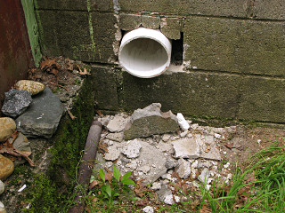
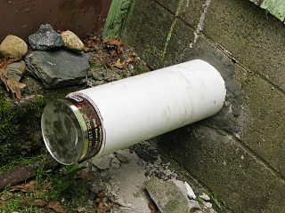
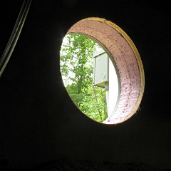
Big PVC pipe through hole in block wall With the main unit finally running, I got my next homework assignment: finish making the holes for the big six-inch duct pipes to the outside for the ventilation system. This embedded two challenges: more chipping away at the masonry blocks on one side, and cutting a big hole through the window-blockoff sandwidch on the other. I tackled the concrete problem first, as I figured it would need the most patch-up work and some setting time.

I had already gotten most of the way through and had the cinderblock pretty well opened up on the inside, so all that remained was the outer surface that I hadn't wanted to lay naked yet. A little more chisel work got that done, and I even managed to keep the three little pieces that *really* wanted to fall out up in place as I finally fitted the pipe through from inside. My hole was just big enough on both sides, leaving very little slop, and even held the pipe at the correct downhill angle to the exterior so any water inside would roll outward.


I haz mad masonry skillz I was a little leery about my ability to adequately patch up all the gaps, but apparently once given a bucket of Quickcrete and some of the smaller scraps lying here I haz mad masonry skillz. The patching went in beautifully, in fact, and later got finished off with a little concrete-caulk to fill in a couple of minor gaps. That pipe was in totally rock-solid afterward and at the perfect slight downhill slope. I used fast-setting quickcrete which gave just the right working time, just hand-mixed in a bucket and squished into place with a latex glove on, and I'll note that the stuff is still quite friable until it cures completely -- so once it's satisfactorily formed into place, leave it alone!

Another fun discovery was that a large coffee can was the perfect thing to plug the open hole temporarily -- slit down one side with shears, it could form a gentle cone that wedged nicely into the six-inch opening to keep bugs and weather out when it wasn't actually venting.


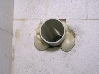
Pipe scrotum Next step was to foam-fill inside the cinderblock holes and around the interior space, which took on a somewhat anatomically amusing shape as the foam expanded. Yes, this got cut back later...

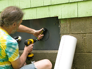
Cutting the biggest. hole. evar. Then came the intake-pipe side. For this I needed to cut The. Biggest. Hole. Evar. through my new PVC/XPS/wood wall section, and I was already on my second Malco cutter bit about halfway through this. Frequent clearing of the bit was needed, but in general it worked quite well and right here is the exact use I had in mind when I was shopping for the cutter. This very hole, where a typical hole saw would simply fail or make a total botch out of it. Everything else, like for the power and the lineset and whatever else, was secondary to this monster.

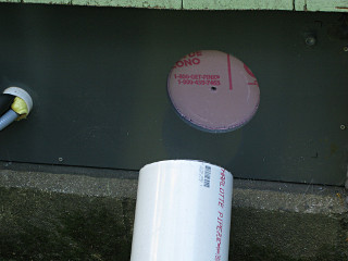
This will be a perfect fit... Big hole really shows the insulated sandwich
A quick test fit showed that I'd set the cutter radius perfectly, and the pipe would go in with zero slop. Awesome. In comparison with the PVC the wood inside was easy to cut, and soon I had the intervening foam sawed away and the whole thing open. Since I'd run the starting guide hole at the correct tilt, this pipe would also be held at a slight downhill angle. This really shows how the "sandwich" looks in cross-section. Again, a bead of caulk got run around the PVC-to-foam and wood-to-foam points and squished into the gaps, to back up the inner and outer air sealing, and after that cured I ran the pipe through and sealed its support points with PVC cement and caulk.

While the sandwich would hold this pipe perfectly, I was a little concerned about its ability to hold up weight hung off the end. The sandwich is only three inches thick and has two thin bearing surfaces, and the outer PVC panel is a bit flexible, so hanging a big heavy elbow and riser on this might need some additional support. It was around here than I started getting the idea for a strong attachment point above each pipe for some extra bracing -- to be engineered after the wall was rebuilt.


Two big holes in my house So now I had two big holes in my house, which ultimately would hopefully become the *only* two authorized places for air to go in and out of when the rest was closed up. In other words, controlled ventilation as the HRV would eventually provide.

However, actually obtaining said HRV seemed to be almost impossible. Webb kept losing my installer's order for it, so over several days when he thought they'd either deliver it or he could pick it up it wasn't there, and then one of the days that week they did deliver one but it was the wrong model. Well, that particular eff-up was actually because the *installer* tried to substitute a slightly different unit that he thought "might do", but was *not* the one I specified and didn't have the full feature set I needed. I managed to intercept that one before it even came off the truck and sent it back, insisting on the 1405R because it would have the quick defrost feature which is also a configurable inlet for the basement air right next to the unit inside. I had my reasons for needing this and having a firm spec on the required unit, and thought it a little unprofessional to make any assumptions otherwise. Another potential nail in this installer's coffin, perhaps.
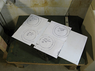
HRV top panel mockup But we needed to get the ventilation ductwork installed -- not a really big job, as it would be a fairly simple layout. I threw together a quick life-size paper mockup of the duct connections, approximating the dimensions of the yet-to-be-correctly-delivered HRV, so that with it in place up on a milk crate on the table he could at least have a ballpark target for the duct ends.

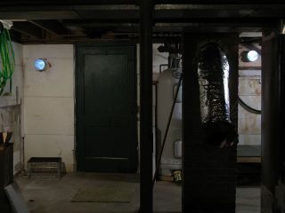
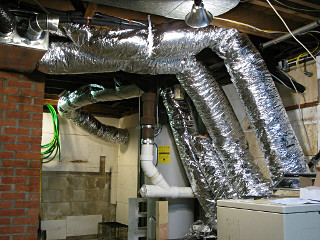
Weird alien silver tubes everywhere So he put most of the runs in and just left the HRV-side flex duct cut a little long to get trimmed up once the real unit was in place. This was the most jarringly visible HVAC change in the basement, with all these alien-looking silver tubes running around, and the short intake hose wasn't even in place at all yet. I was slightly concerned that the fatness of the insulated duct would start to diminish headroom, but even the far exhaust tube tucked nicely up against the joists, leaving swing room for the door, and was totally out of the way.

Another bit of magic, or at least astounding coincidence, happened concurrent with running this ductwork. The exhaust pipe was the longest run and would be going out the wall, and something would have to prevent outside air from coming back in under wind pressure or whatever when the ventilator wasn't running. It needed a backdraft damper, essentially a one-way check valve for airflow, and rather than the typical klanky metal-flap type that we often hear rattling on a windy day I opted for a more elegant solution. I had just ordered a Cape backdraft from Tamtech that week and figured it wouldn't arrive for a few days and I'd have to install it later, but it showed up *this very day* via UPS, just in time to be worked into the project. Literally -- The HVAC installer was just starting on the exhaust hose and went out to his truck for something, and came back saying "were you expecting something from UPS?" -- and there was the box with the damper sitting on the doorstep. Next-day service, from generic "UPS ground". We worked it right in, using its own tube as the connection from the inner core of the flex duct into the PVC pipe.

This all happened so fast and I got a phone call in the middle of it, that I never got a picture of the damper going in before it was all fastened up and done. But a quick look at Tamtech's website link above makes it pretty obvious how the damper works.


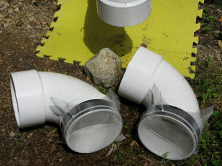
Quick-n-dirty weatherhoods for HRV On the outside I test-fit a couple of the PVC elbows which would eventually connect upward to short risers, but for now a couple of simple bug-screened hood equivalents would do until snow season.

The yellow pad was part of a small set of those padded interlocking neoprene tiles they use in things like playgrounds, that I had trashpicked a few days before. Much nicer to sit or kneel on while working out here.


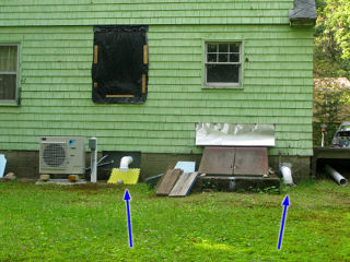
Back of house appearance with all this new stuff, vents The back of the house was starting to look a little different with the addition of the Daikin unit and the vent pipes, and the downward elbows would pass air but keep the ventilation stuff completely out of the way of the insulation job. I'd worry about raising the inlet/outlet later on.

Next section   (07)
Index

_H*   120702