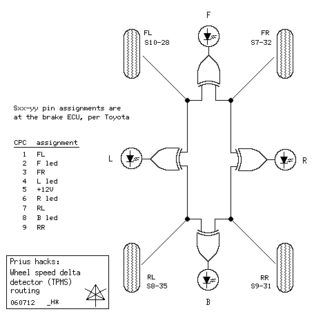
Routing

This is the overall hookup in the car, using four XOR and driver circuits.
Signal and output routing is quite straightforward, and the diamond
configuration gives a positionally-sensible and visually immediate look
at relative wheel speeds.  There are several more interconnect points than
just the small CPC, and three layers of wire-color and pin correspondence
where things could have gotten crossed up during this particular installation,
but once those are connected their specifics aren't important.

XOR is one of several methods for detecting relative phase of two waveforms,
usually used in phase-lock-loop circuits.  Note that the XOR output changes
at *twice* the nominal add/cancel beat-frequency between the signals, which
must be taken into account when doing any calculations based on timing the
brightness changes at the LEDs.
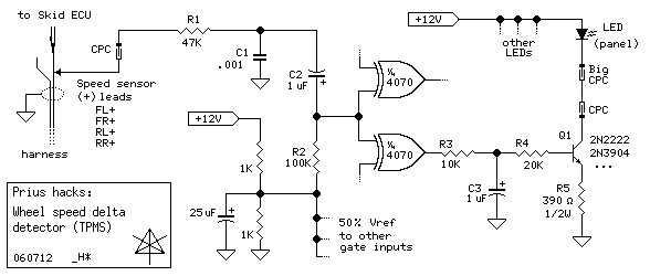
Circuit discussion

The un-numbered 1K/1K ladder is common to all four circuits, and derives a
50% reference voltage level between 6 - 7V depending on battery voltage in
the car's electrical system.  A nominal 13.8V is also fine for powering
the CMOS quad-XOR chip.

The signal in question is tapped in the usual slit-n-solder fashion, and
brought in through a network that does not cause any interference with the
sensor or the car's ECUs.  The speed sensor at the wheel is a pickup coil
with an impedance of about 1.5K, and R1 more than suffices to isolate any
possible loading effects away from the normal signal path.  C1 applies
a little token noise-filtering.  The maximum frequency we would ever see
here is slightly over 1 KHz, if the car was doing its absolute top speed.
One reason this hack works at all is that with 48 teeth around the sensor
wheel, the frequencies generally encountered are high enough that determining
a delta is a reasonably fast process -- as it indeed must be for ABS itself
to be effective.  Thus the sensor basically produces an audio signal, and a
reasonably healthy one at a volt or two peak-peak.

The signal is AC-coupled through C2 into a bias network that floats the
XOR gate inputs near half the supply voltage.  The coupling cap polarity
accounts for the fact that the 1.2V bias of the sensor is below the 50%
reference bias.  The gate treats the 50% level pretty much as a "maybe"
bit, becoming a high-gain and not very linear amplifier in a small region.
Because of this, output with the car at rest is INDETERMINATE, and may show
LEDs arbitrarily on or off depending on internal gate threshold differences.
By about 3 - 4 miles per hour, e.g. creep speed, the sensor signal swings
with sufficient amplitude above and below the 50% point to assert a solid
1 or 0, and the XOR gate can then produce output based on phase difference
which swings nearly rail-to-rail.  This is a completely unorthodox method
of CMOS interfacing, but it keeps the parts count much lower.  The re-biased
signal is split to two gates, where it is XORed with either adjacent wheel.

Gate output is low-pass filtered by R3 and C3 for a cutoff beginning at
roughly 16 Hz, which corresponds well with where human visual response starts
becoming unable to clearly distinguish a flicker rate and perceives a steady
level anyway.  The resulting voltage is turned into a current through the
panel LED by the emitter-follower at Q1, letting the LED's brightness fairly
accurately mirror the filtered XOR output.  All the driver components are
down on the XOR board, leaving only the mounted LEDs and minimal wiring
needed up at the gauge panel.