Two years later...

A post-discovery retrospective, and a new supporting theory

In the two years following discovery of the MFD problem cause, I fixed two more units for other people, almost grudgingly collecting a nominal sum for the work. Not exactly the booming MFD-exchange-fixit sideline I thought might possibly start up ... but not only did those two other units have the exact same problem, almost everyone reporting in on the original thread who dug into their own units far enough found the same situation and often managed to fix them the same way. That's rather gratifying -- i.e. just finding out that I was right about the problem, or maybe just plain lucky, and being able to help the community in a tangibly useful way. That's really a better reward than a few bucks to fix more screens.

[A third local potential customer brought me the entire car one day, but a quick look at the hairline crack all the way across the glass under the touchpad surface told me she had a very different problem. I pointed her toward Steve for a replacement unit with the suggestion that the screen itself might be able to swap between NAV and non-NAV equipped units; I don't know if that worked out or not.]

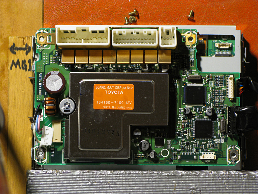
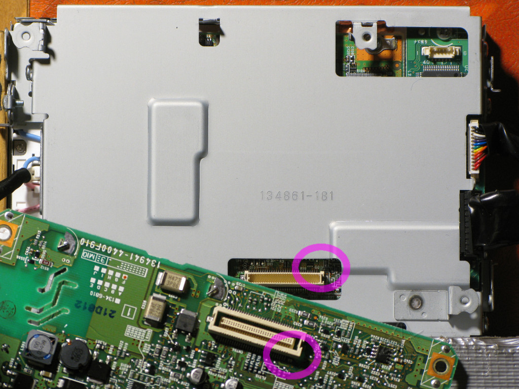
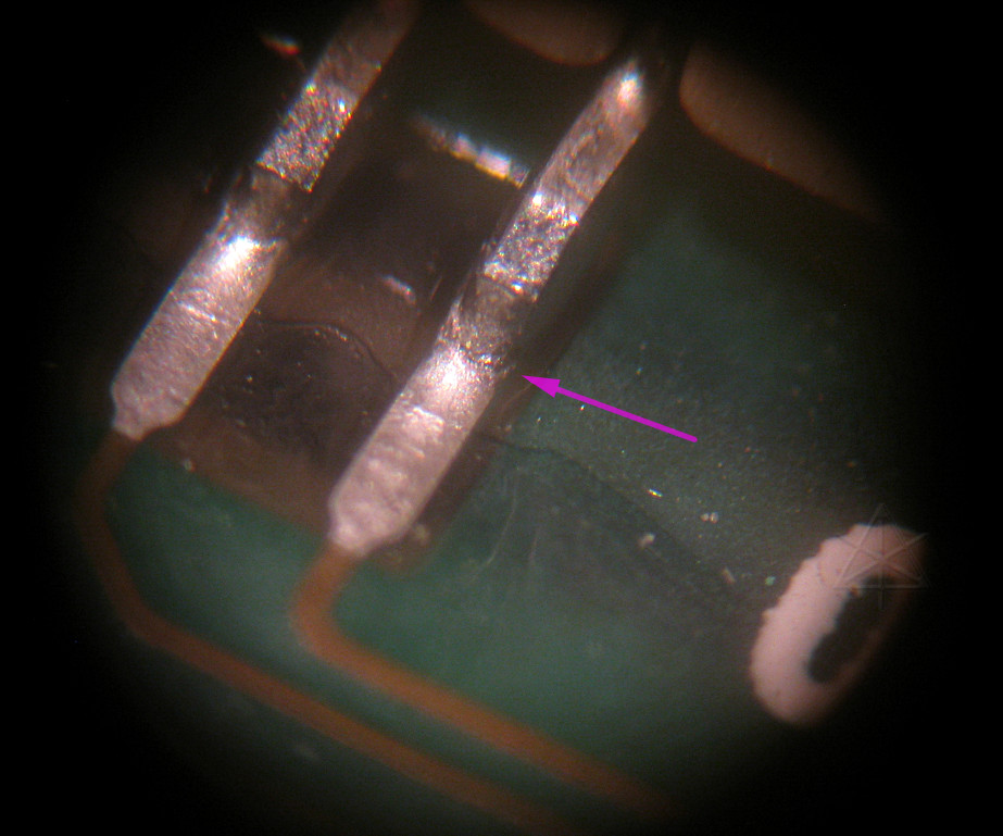
In the process of disassembling subsequent units, I noticed another aspect of how they're are put together that could have contributed to the problem. I took the opportunity during my second "professional" fix to try documenting this carefully and offer a possible preventive measure that if done early enough, could stave off the connector problem indefinitely without any soldering.


Our second fixit-for-pay unit, said to be exhibiting the same symptoms of sluggish response and no battery or MPG display.

While disassembling it, I confirmed what I had come to suspect over time -- once the screws are out of the rear board and it's attached by nothing other than the white fine-pitch connector, it doesn't want to quite line up the way the screws were holding it. It in fact wants to cock just a little bit to the right.


To show the very minor difference in board alignment before and after the screws are removed, a heavy holding jig had to be constructed out of a couple of bricks [wrapped in duct tape] and scrap wood [part of an old "lever arm" demo I used to try to describe how HSD works]. The camera was on a solid tripod straight above this and not moved or even powered off between the two shots, so the position, lighting, exposure, focus, zoom etc are exactly the same between the two pictures.

The MFD was aligned into the jig along the bottom brick, shot, taken out to have the screws removed, and put back into the jig after wiggling the rear board a little and letting it "settle" to the position that the white connector's alignment really wanted it to be in.


This is an animated GIF, so if you're blocking
animations you won't see what's going on here.
There is a visible difference between the factory-assembled alignment and the "settled" position that puts no twisting stress on the connector. It's still within the limits imposed by the little alignment tabs from the frame sticking up through holes near the upper screws, but takes some palpable force to cock the board all the way counterclockwise against the screw shanks as it seems to come from the factory.

The flexible floating center of the upper connector is supposed to absorb any mispositioning, but being off-center still places a steady force in one direction against the parts.


The locations of our problematic pin 60 are circled; the one nearer the bottom of the picture is the rear-board half where the solder fix gets done. Assembling this and torquing the rear board counterclockwise applies mild stress that tries to both pull and tilt the rear-board connector half *away* from pin 60, very possibly contributing to it tearing itself out of the solder fillet after miles of pounding on the roads. Perplexingly, the inner connector half never seems affected by this.

In this particular unit, we once again have what's become the textbook solder joint crack. Time to fire up the tiny-pointed iron and reflow it.

Connections fixed, a couple more nearby also reflowed just in case they were also starting to weaken [with a little bit of our ol' reliable 60/40 "Preservation of Hazardous Substances" certified solder added], and a klunky "signature" applied with a fine marker.   [Hmm, did I really need to watermark this pic??]

But the other important thing is that during reassembly, the four screws are partially threaded in but the rear board / connector mating angle is allowed to settle to its more relaxed position before the screws are actually tightened down. I'm really thinking that just doing that may actually help not-quite-failed-yet units continue working much longer than they otherwise would. Perhaps two more years hence and if enough '04/05 owners try it before their units actually fail, we'll actually be able to tell if it helps.


Back to main page

_H*   100124