As New England *finally* escapes the grip of its bizarrely-timed winter,
the car is ready for a service item which isn't strictly due by the book, but
has been discussed in several forums as a good idea.  Toyota says the fluid
fill in the '04+ Prius transaxle is supposed to be good for 120,000 miles in
"normal" service [whatever that is, given that they tell you not to tow with
it in the first place] but the people who have sent some of the used stuff
in for testing report that the fluid in the 3rd-gens is basically used up at
50,000 miles and in the Classics, even sooner at 30,000 or so [at which time
upgrading from type T-IV to ATF-WS is regarded as a good idea for those cars
too].  Wear metals, climbing viscosity, the whole nine yards.  So in light of
a certain milestone attained late one winter night...

and by now at 53 K or so, it's time.

This is mostly about the transmission fluid change, but also gets into a few
other maintenance items.  An all-four inspection of the brakes, also on the
todo list this spring, is detailed over here.
|
Clarification Let's be clear here. The following exploratory procedure is *not* how you want to be doing routine transaxle-fluid changes. What wound up being detailed here has apparently confused the Prius community for some time, and y'all have my profound apologies for that and any extra work it may have caused. For a more routine procedure, albeit with the caveat that you cannot remove the bottom pan on a second- generation car, see this page in which we changed the fluid on a first- generation car that had possibly never had it done. So no, you certainly don't have to uproot your inverter every time you go to change the tranny fluid. Just drain and refill with your Very Long Funnel at the front inspection plug and be done with it.
|
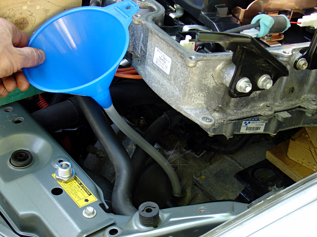
There are THREE access points to the transaxle fluid -- the drain plug, the
level-check hole on the front of the case, and one that is rarely mentioned
on *top* of the transaxle case.  This latter seems like a logical place to
refill from, since trying to get oil to flow horizontally into the level check
hole would take a *very* long funnel or a lubricant pump.  It should be noted
that the Toyota service manual does specify refilling via the level-check hole
with a pump or a long tube, and is likely a faster, less involved process.
However, one goal of this project is to see how far the inverter can be shifted
upward/around *without* having to drain its coolant, to access any items
underneath or the sensors on the left side of the engine.  With the '04+,
there is actually a bit less stuff hidden under the inverter than in the
Classic, but many service procedures still begin with "drain coolant and
remove inverter", so it's time for a sanity check on just how necessary that
is.  At any rate, it's definitely got to be displaced to allow access to that
top transaxle fill hole, so here's how to go at it.

Use the image links to the larger pictures to clarify everything.
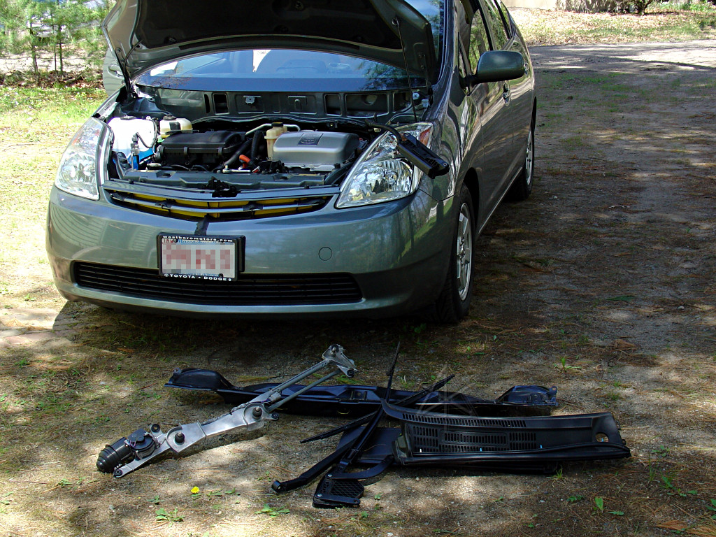
Follow the "heatgames" page instructions to remove the wipers and cowl.
Remove the plastic radiator-area cover, whose six clips are easily released
with a Phillips driver [but they're *not* actually screws!].

|

|
Ensure the car is powered down, the smartkey disabled, and inexperienced
personnel kept out of the work area.  Make the electrical system safe, and
wait the specified 5 minutes for inverter capacitor discharge before
proceeding.  If you don't know what you're looking at here, maybe this
isn't for you after all, but reading the battery current page might help.
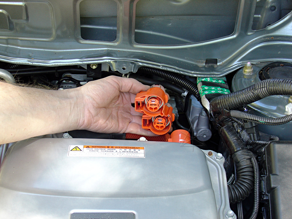
Disconnect the battery leads from the back of the inverter.
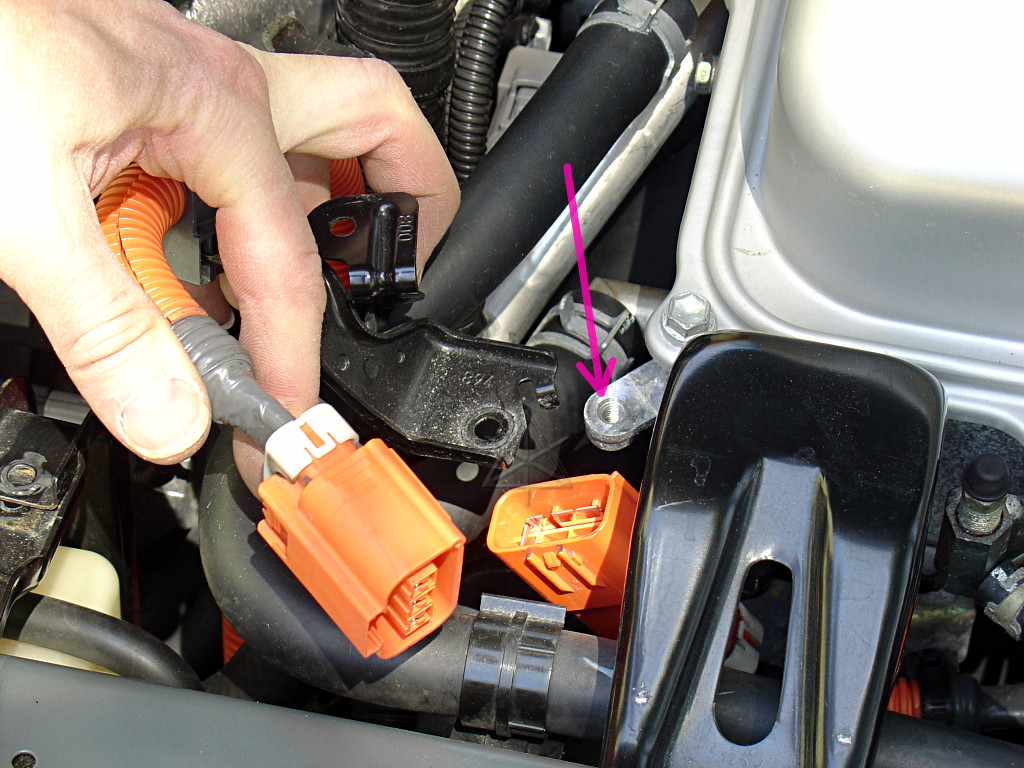
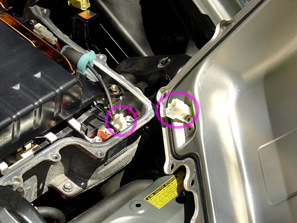
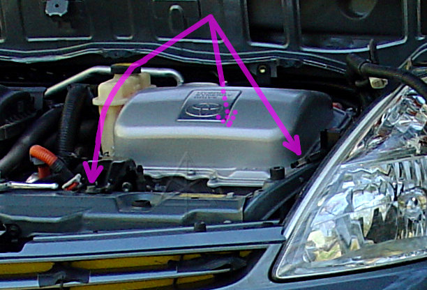
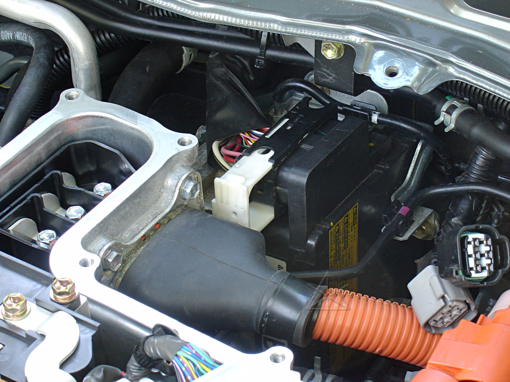
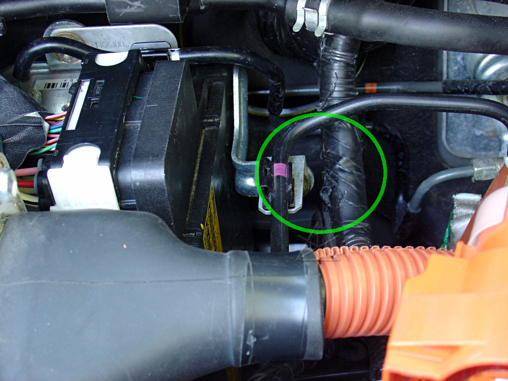
Unplug the A/C connector, and just to make things easier, unbolt the entire
bracket from the corner of the inverter [pink] and lay it back along with the
wire next to the engine.
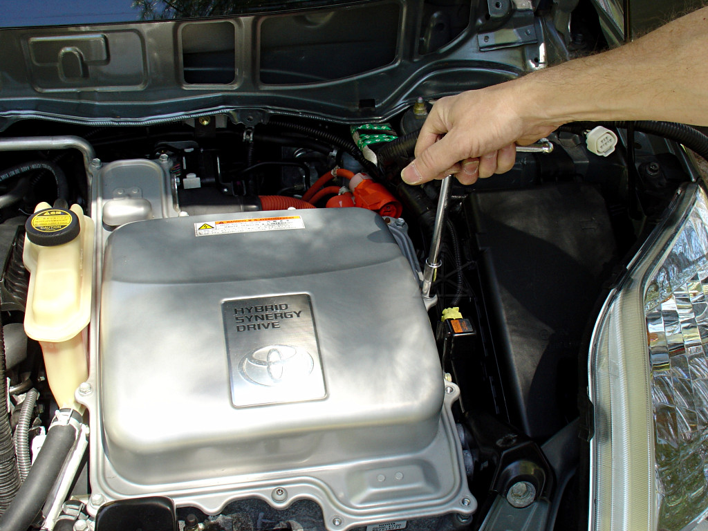
Start unbolting the inverter cover.  See the shadows falling on it?  That
proves that this technology *IS* accessible to the shadetree mechanic.
There is ONE T-30 Torx bolt somewhere around it you'll have to deal with.
Gently crack the gasket and lift the inverter cover off.  Note the interlock
plug near the front; this needs to mate properly when the cover goes back on.
Check the copper bus bars around the capacitor module for any remaining
voltage between them or to chassis ground -- there shouldn't be any.
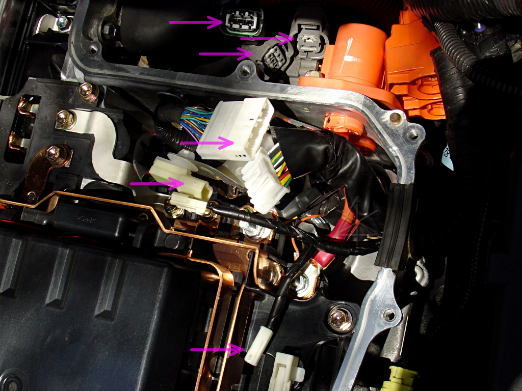
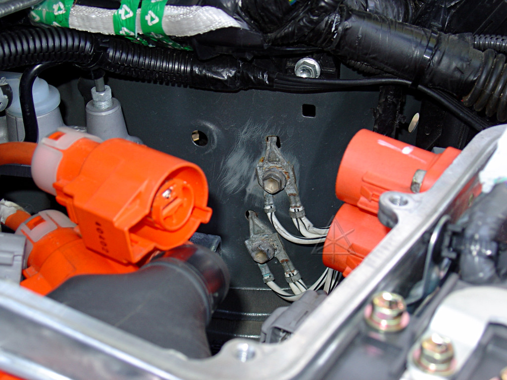
Unhook the three connectors behind, and the three connectors inside the
inverter [pink arrows].  The latch on the lowest one in the big picture, with
the interlock wire, may need some gentle persuasion with a small screwdriver.
The yellow impact-sensor connector on the side is a special airbag-style
latch, which pulls back to disengage [easy] and also to reconnect [totally
non-intuitive].
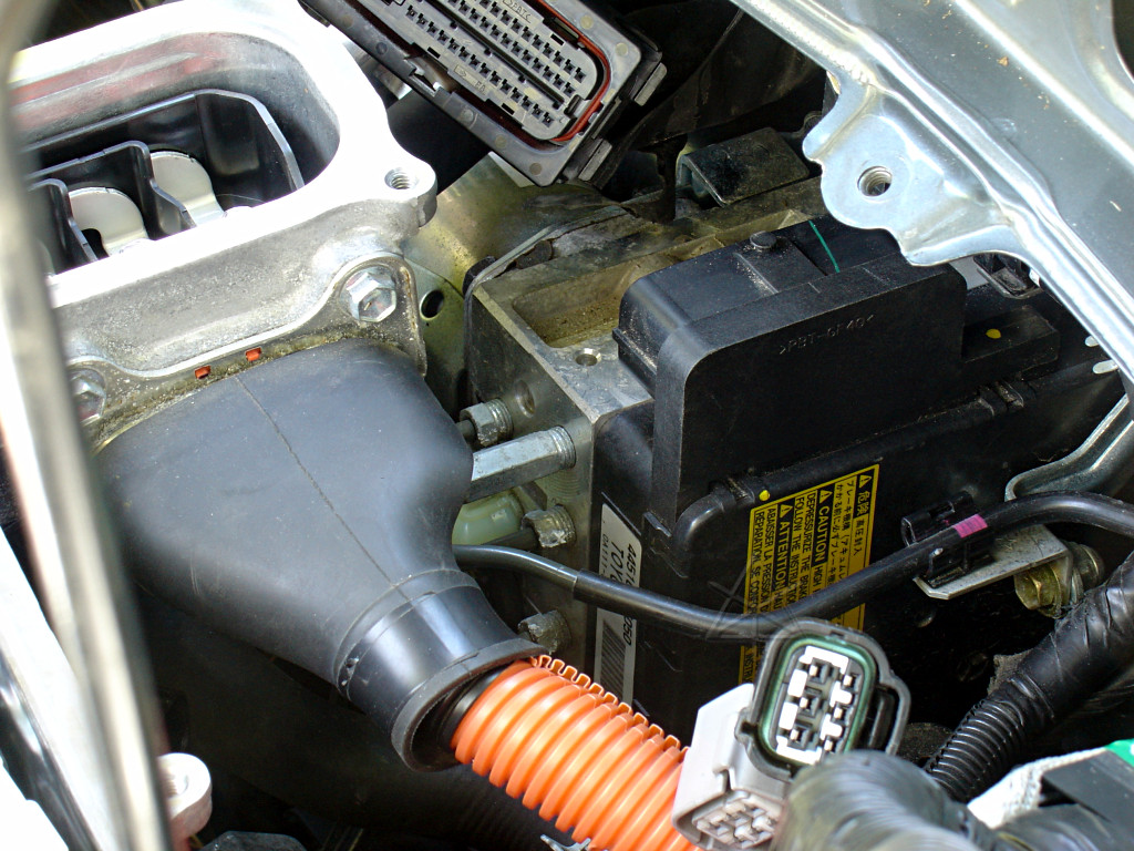
Lift the harness gland out of the slot in the inverter case and push the
group of connectors back out of the way.
Remove this bracket, leaving the section that wraps around the A/C hose.
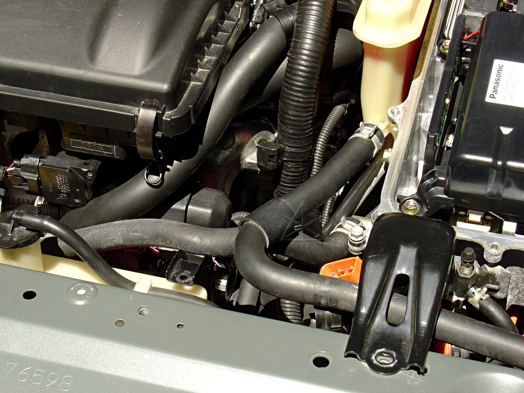
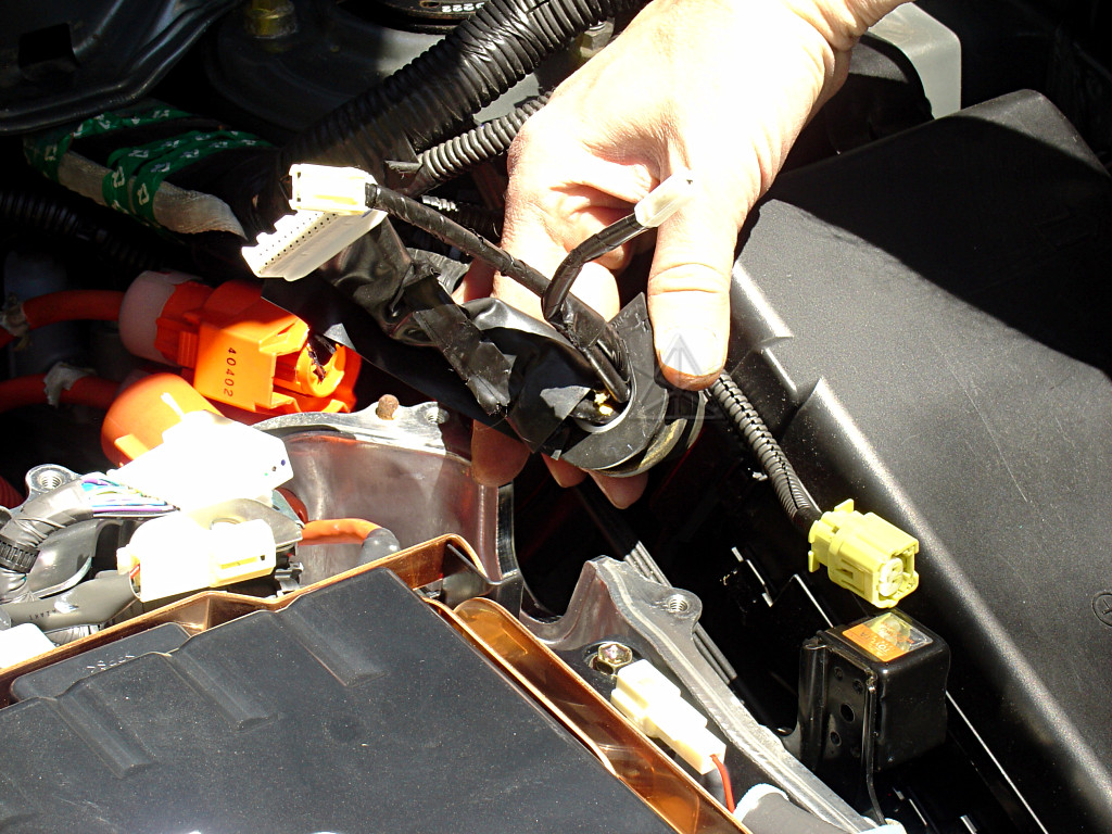
Tease both inverter coolant hoses up out of their clips -- note that the
one toward the passenger side neatly clips in along the bottom of the
engine coolant tank.  Raise both hoses up above their clip points, so
they can follow the inverter when it gets lifted.  Take note of the thinner
coolant bleed fitting and hose on the front of the inverter; this will be
one of the main movement limiters.
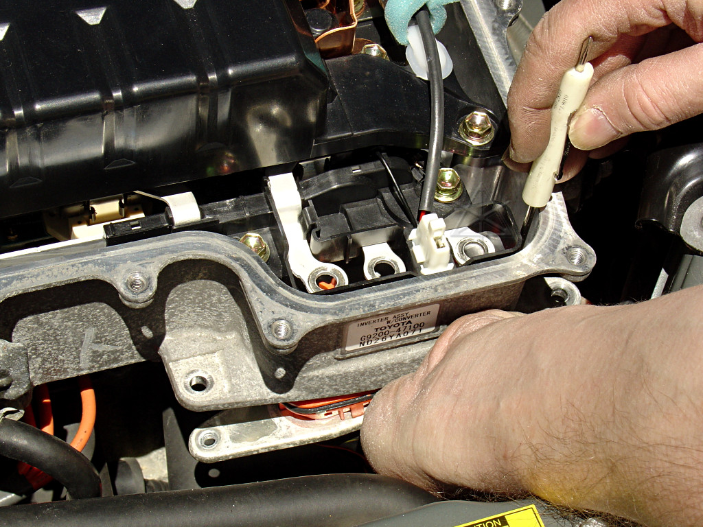
Unbolt the three electrical, and two attachment bolts on the MG1 connection.
There are a couple of small latch barbs that need to be released with a
screwdriver before the connector can drop out of the inverter case.
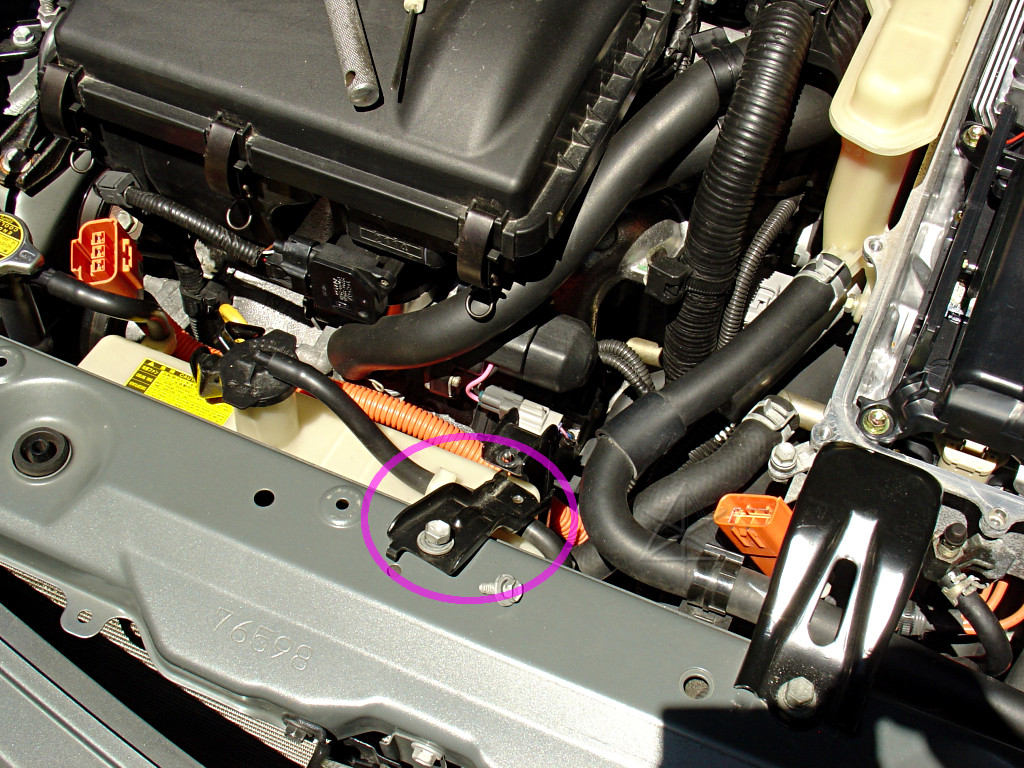
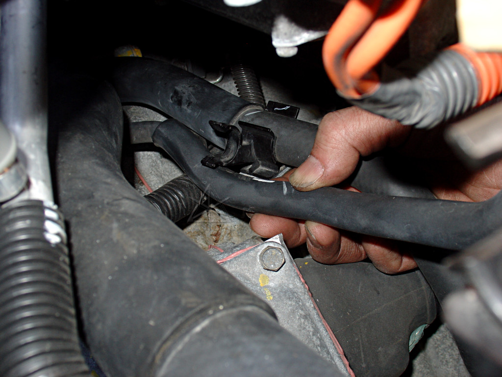
The inverter is held in with three largish bolts -- the third one of which
is fairly far down behind the inverter.  Look straight down, you'll see it.
Between the three of these, one bolt hole is small, one is slotted right/left,
and one is larger and round.  This allows easy matching to any variations the
car body geometry may have.

Now, this part isn't necessarily for everyone.  The inverter is fairly heavy,
and as it moves around it shouldn't be allowed to sit its full weight on
anything delicate such as brake lines or hoses or wiring.  Get help to lift
and hold things as needed.

The first thing that should be done once you can get a hand underneath the
inverter is unclip the small coolant bleed hose from where its midpoint is
held to the transaxle case.  Follow it down from the bleed fitting on the
front, and see some of the later pictures for how it's fastened in.  This
will allow the inverter to rise farther.
Shift the inverter toward the front of the car to gain enough space to release
the brake-actuator connector retainer.  Look down behind the inverter and
try not to let the support bracket drop completely off the mating bracket
that it bolts into.  This can be fiddly -- the actuator connector latch pulls
forward quite a ways before finally disengaging.
This allows unplugging all the braking control wiring for cleaning and
inspection, and once the connector is out of the way there's a little more
room for the MG2 connection bump on the inverter to sit in there.  Check the
short actuator harness for any wear on the bottom as it comes from the
firewall and rests against the actuator block, and re-bend the wiring a
little if needed.

Now, with the whole brake actuator disconnected, with no accumulator pump or
pressure sensors or solenoids, what do you think happens when you open the
driver's door?  Don't worry, that OMFG-everythings-broken beeping will stop
happening once this is plugged back in.
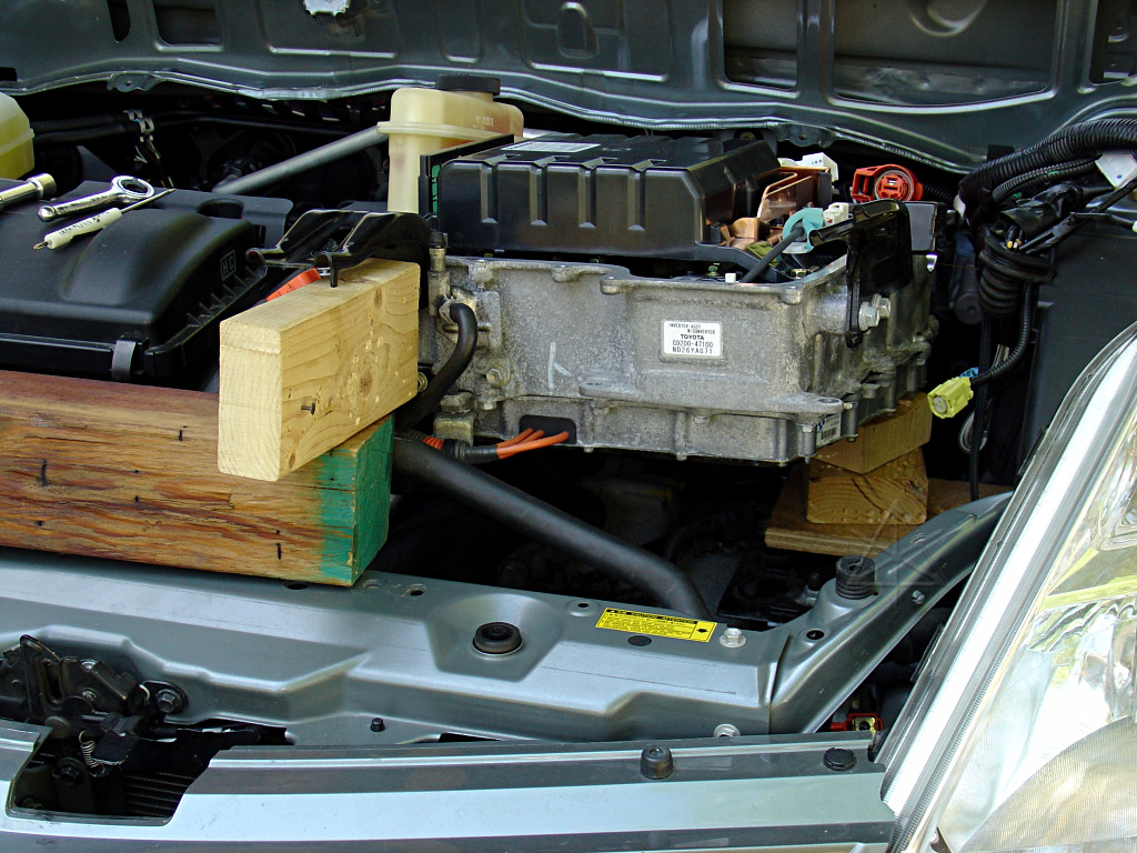
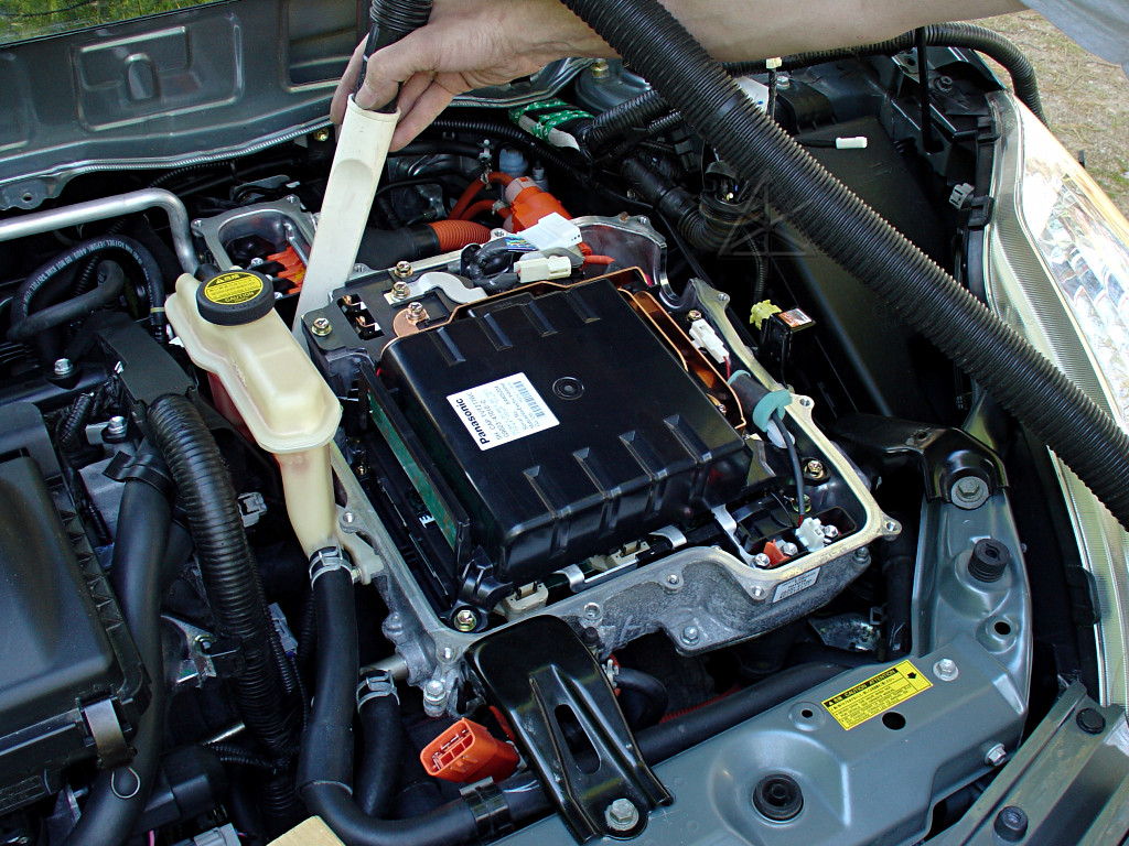
Support the inverter as high and as well as possible, using any available
objects.  Wood blocks are good.  The main limiting factor is likely to be
the bleed hose, and to a lesser extent the inverter radiator hoses.  Again,
make sure the back end isn't resting on the brake piping; use additional
supports under the rear bolt bracket.  The inverter can be solidly supported
up this high, which is enough.
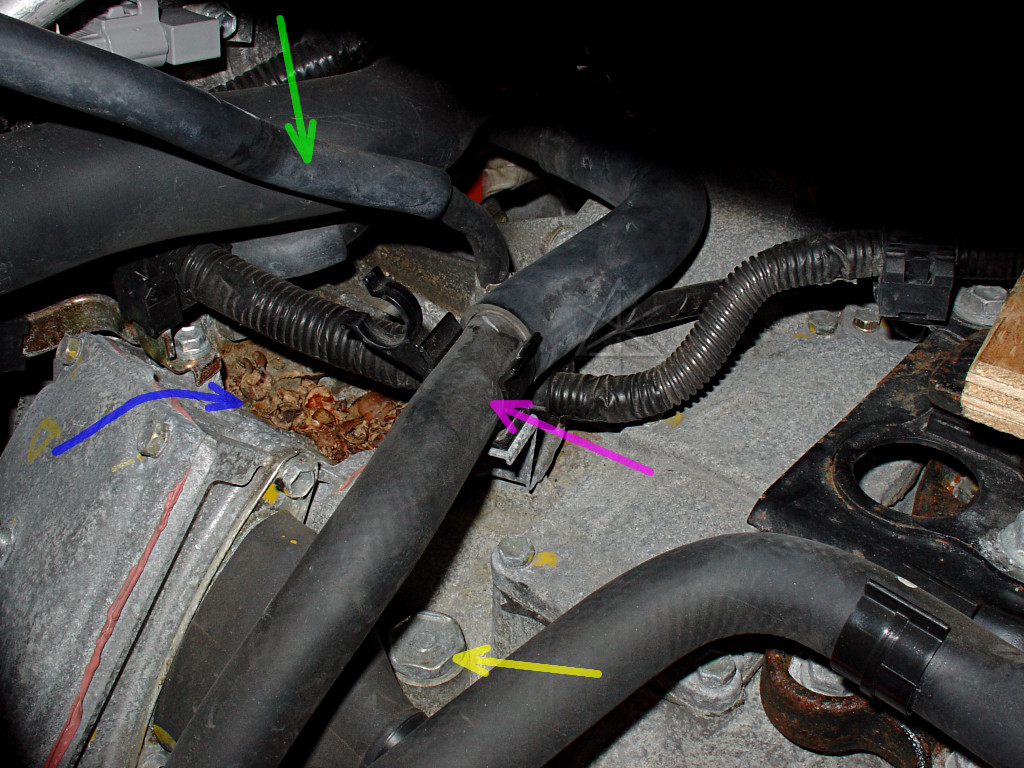
Now we can delve into the dark mysteries underneath.  Several things now come
to light: the transaxle fill plug [yellow], where the bleed hose [green]
hooks up, and an engine coolant hose [pink].  And evidently a little gift
from the local rodents [blue], and it's high time *that* was vacuumed out
of there too.
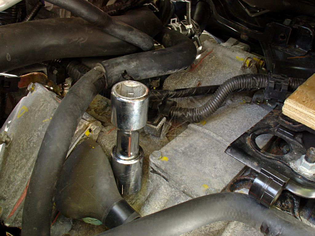
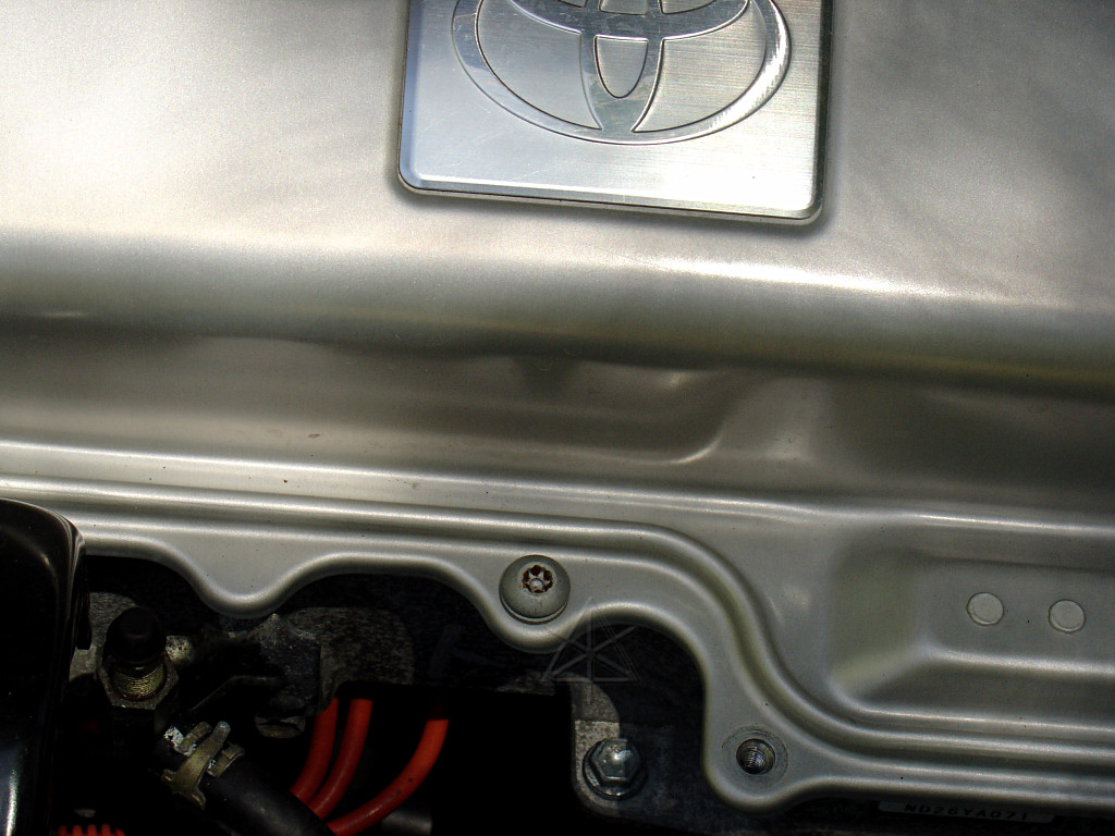
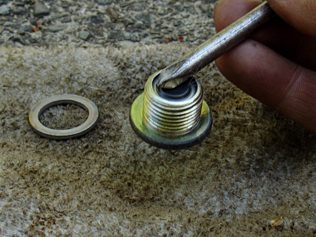
With the hoses out of the way, now you can finally clean around that top plug
and get a wrench on it.  24mm, but 15/16 is very close to that if your only
"huge sockets" set is english.  It's useful to open this first, because the
fluid will drain much more nicely without going glug, glug and making a mess.

Now, as I cracked this plug, I noticed a *long* period of hissing air intake.
As noted by various forum members, the transaxle evidently accumulates negative
pressure, which seems odd and a higher risk for dirt ingestion, but given that
pressure relief clearly happened as the plug was opened it appears to have
remained sealed without mishap so far.  Upon reflection, negative pressure
is clearly better than positive pressure -- it would help keep various seals
from leaking [notably, the axle seals, which have quite a bit of radial slop].
The air fitting on the MG1 connection cover [very left edge of the picture,
partial] is some sort of one-way valve to let air out, but not in.  Here's a
deep study of the equivalent valve and its function on a Classic, and a
pressure-relief breather mod.
Nothing unusual about the top plug; hints of pink on the inside.
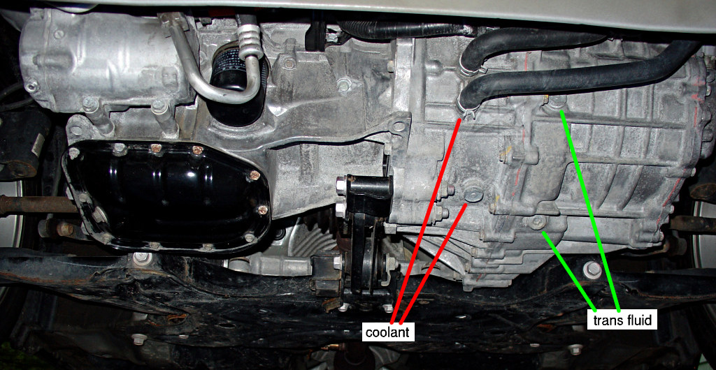
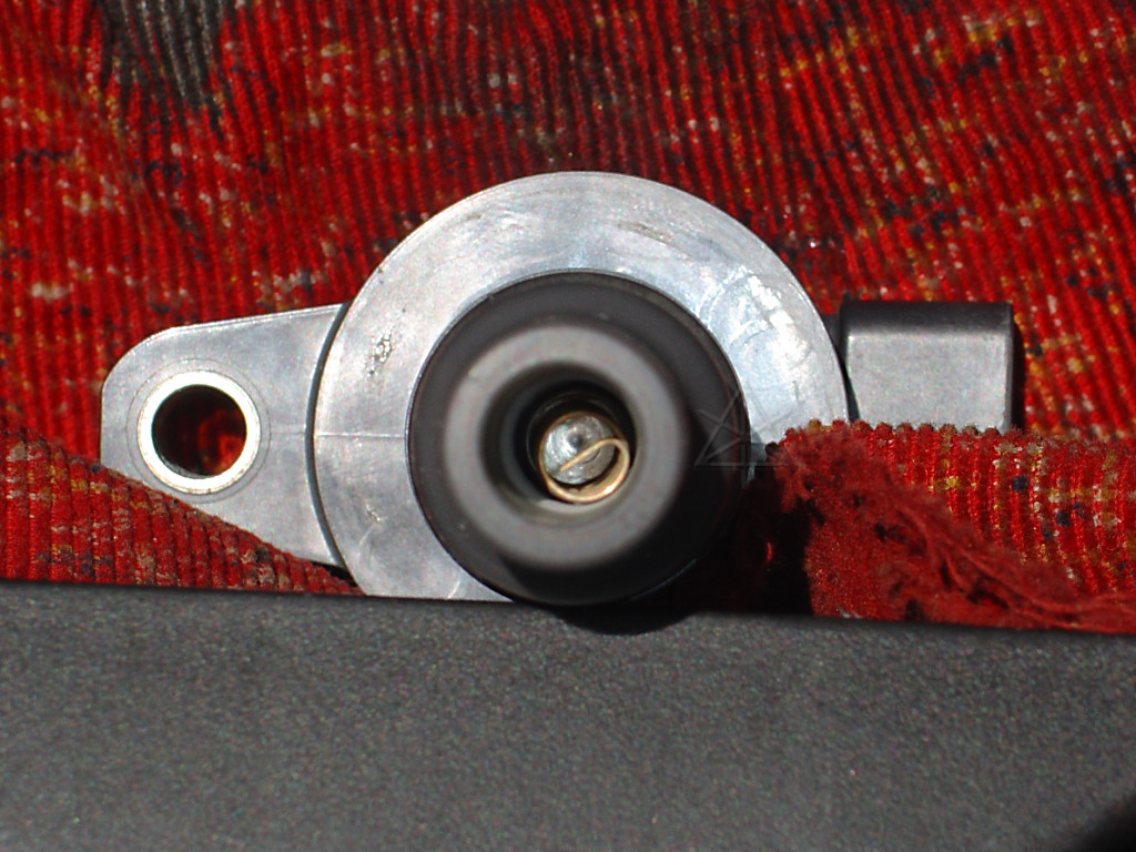
Now we shift perspective to underneath the transaxle.  If necessary, lift
the car slightly to unload the suspension and get more room underneath, just
like when changing oil.  There are TWO drain plugs on the transaxle -- we
DON'T want the one for the coolant [red X!] -- we want the plug with the 10mm
hex hole in it [green], that inexplicably does NOT look like the top or level-
check plugs whereas the coolant plug does.  And of course both fluids are
pink.  Look at the big picture for, well, the big picture.  A good mnemonic
is that the coolant plug is in-line with where the two lowest hoses go in and
out of the case.  The tranny-fluid level-check plug is off vaguely in the
direction of the pink arrow.  Don't open that one yet, since it is likely to
dribble fluid now and and may let new fluid splash out during refill.

If the inverter was to be removed completely, at this point you'd only have to
drain the coolant from the other plug and unhook the three hoses up top.  But
leaving that loop intact avoids some amount of mess, exposure to outside air,
and then having to bleed the bubbles out of it.
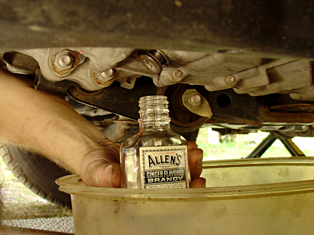
First things first: collect Bob Wilson's fluid sample.  This needed to be done
directly since I was draining into my usual oil-change pan and didn't want
any cross-contamination.  How I avoided getting myself soaked with the stuff
I can't imagine, but to eliminate the potentially more icky material from the
bottom, I drained a little bit, using the plug just barely out of the threads
as a vague approximation of a control valve, and then let a thin stream into
the sample bottle.  The original bottle contents were strictly for medicinal
purposes, honest, and more recently it held the acetone supply for the brief
and 100% unproductive time that *that* test was in progress.  Now it will
serve to carry 53K-old transmission fluid in the name of Science.
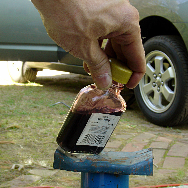
The stuff is pretty dark -- still a pink tinge, but nothing like new.  I'm
a pretty gentle driver and easy on a transmission, but it's probably still
good that this stuff is coming out of there.
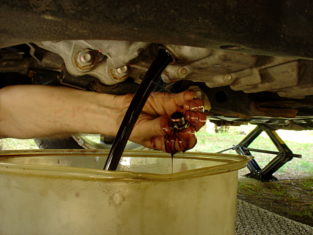
Now, let 'er rip!
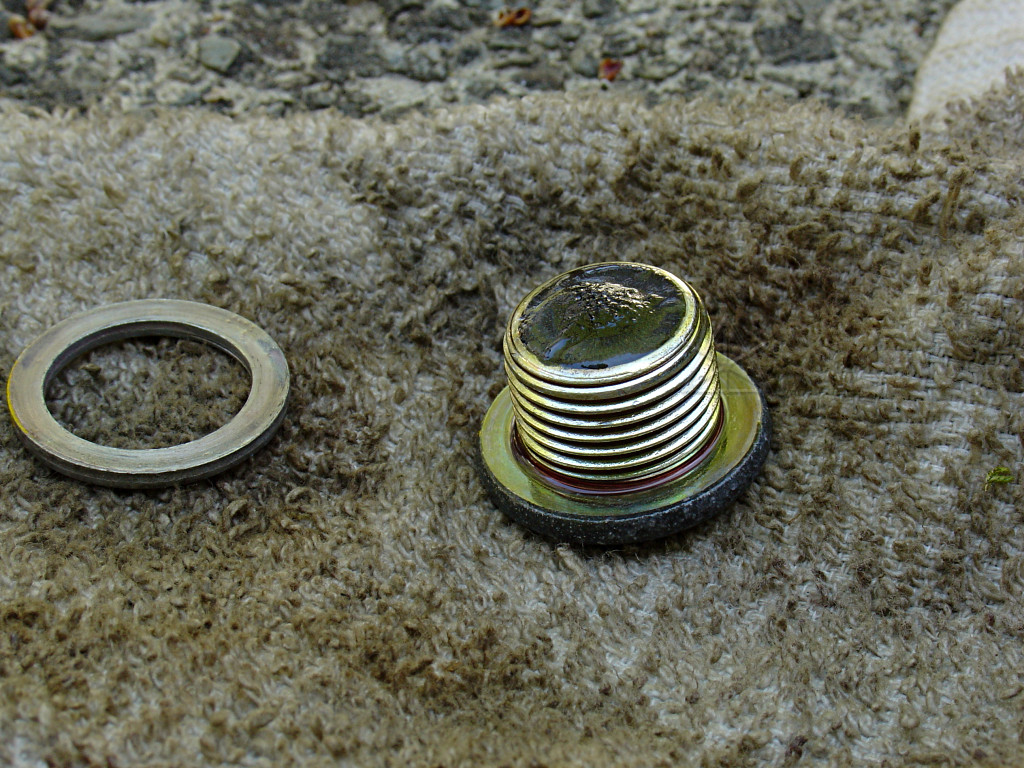
Not too much crud collected on the plug magnet, but definitely some.
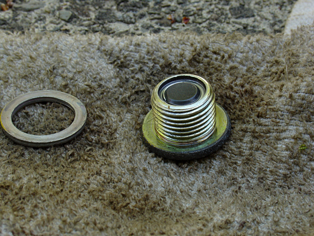
Wiped clean.
The magnet really isn't that strong -- the plug can barely lift itself,
and only when the screwdriver is bridged across the magnet and the outer
rim, i.e. two poles.  It's amazing that MG2's very strong rotor magnets
don't pick up more ferrous crud than they do...

Okay, enough playing.  Reinstall the plug into the transaxle and tighten.
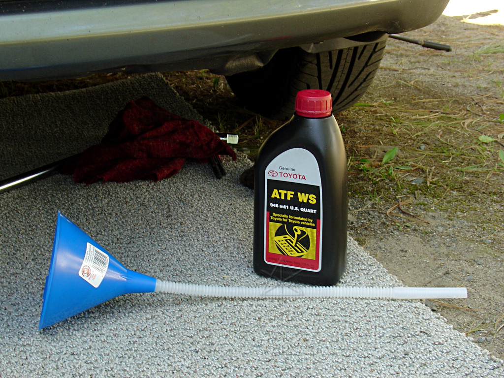
Now, before you went through all that unbolting and inverter-wrestling and
draining, you *did* remember to purchase these two important items, right?
It's cheap, but exactly suited to the purpose.
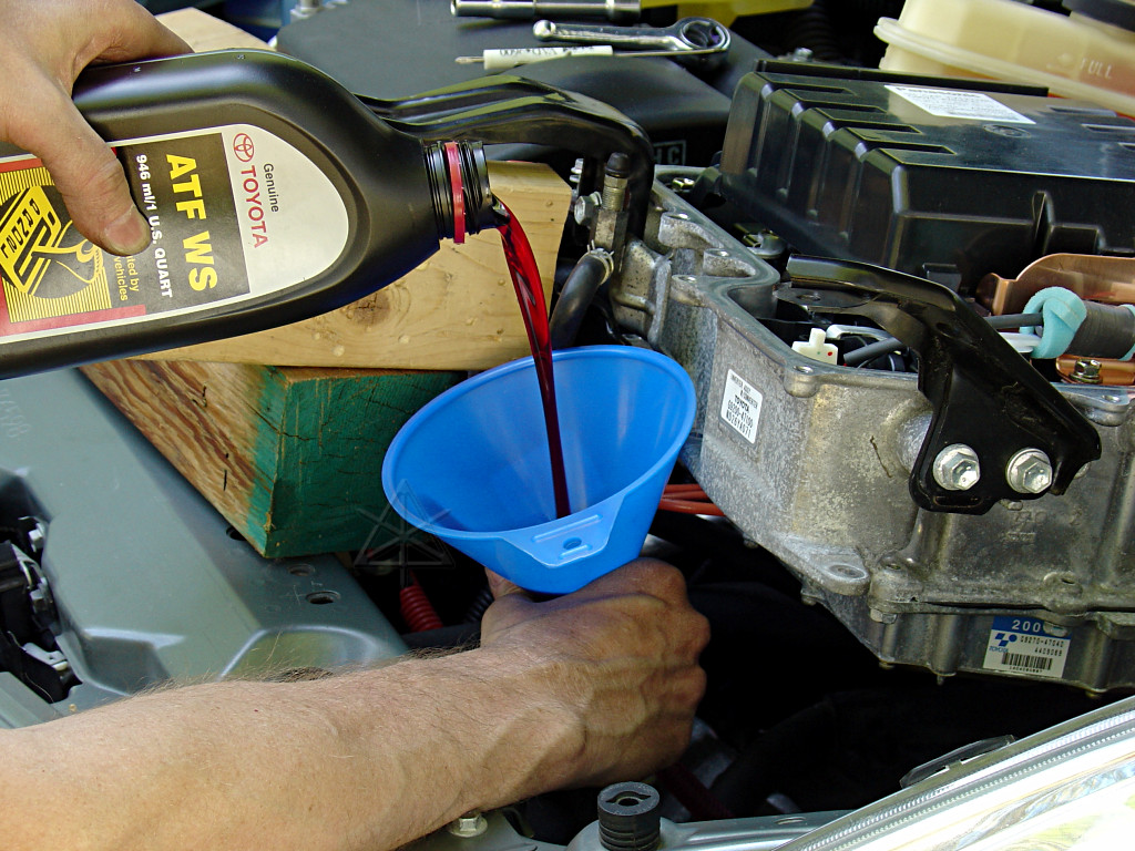
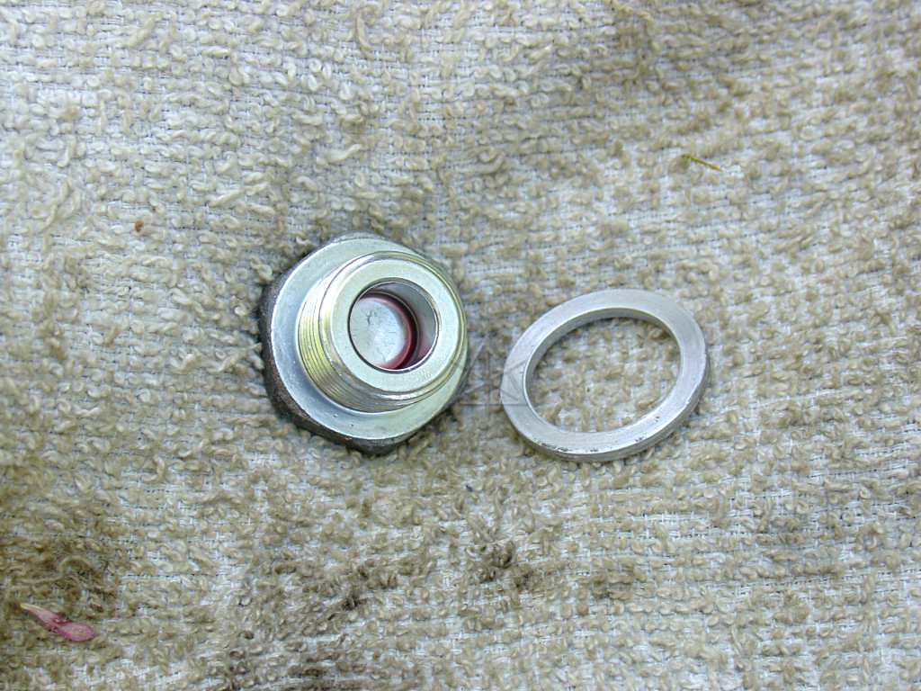
Bombs away!  One quart in, check underneath for leaks.  Two more quarts in,
and finally open up the level-check plug.  Spec is 0 - 5 mm below the level
of that hole; a little finger inserted and dipped *way* down could just barely
find some fluid after three quarts.  About a third of a quart later, it was
almost to the lip, so I reinstalled the level plug and and added a splash or
two more.  So 3.3 to 3.5 quarts seems about right for drain-n-refill, where
the dry spec is a little over 4.

At this point, all remaining transaxle plugs should be reinstalled and
tightened.  In this case I re-used all the aluminum gaskets, since they're
in perfect shape and hopefully I won't have to deal with this for another
50,000 miles.
Having now accomplished the primary goal of changing the fluid, several other
things can be conveniently done with things still open and uninstalled.
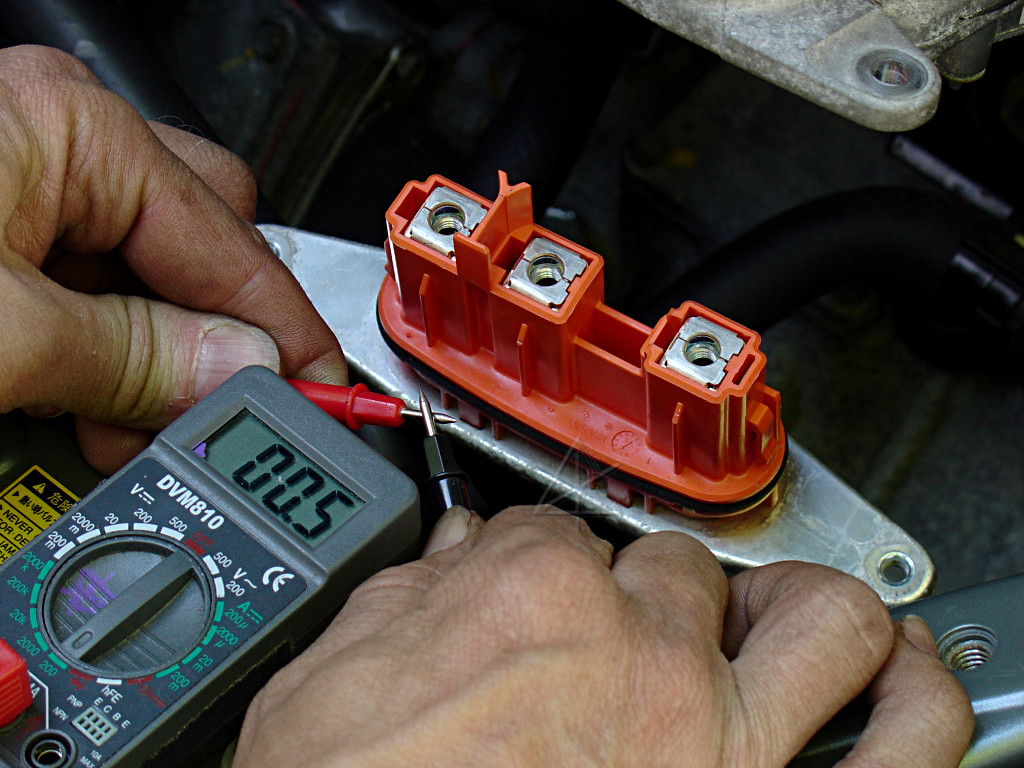
Just for yucks, a quick ohm check on the MG1 windings.  The meter and leads
appear to have a baseline of half an ohm...
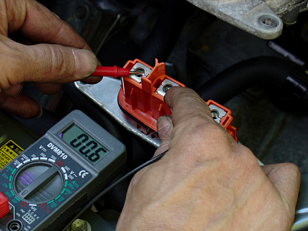
and MG1 adds all of .1 ohm [probably less] to that, between any two leads.
Both MGs are very low resistance, we knew that... you'd need a proper
milliohmmeter to really test this right.
As you go to restore the inverter to its place, be sure to re-clip all the
displaced hoses underneath.  Since the transaxle moves relative to the inverter
and surrounding parts, we don't want anything floppin' around down there.
For the most part, Toyota's done a really stellar job on cable and hose
retention/protection and accounting for drivetrain movement.
Might as well go after and clean up these ground points, too.  In this case
one of the bolts was starting to get a bit of corrosion [well duh, it pokes
through into the fenderwell], and received the benefit of a little emery
paper around the hole and a touch of anti-seize on the threads.  The same
was done not too long ago on the similar pair of ground points over on the
right fender, when the windshield-washer tank was out.  Bad grounding points
are frequently responsible for all manner of subtle car electrical problems,
because they're often overlooked as causes.
Here's another potential cable rub point.  The primary 12V converter output
lead and some other stuff passes very close to, if not touching, a bracket
for a brake line.  I see a little shredded tape here, although there's also
a hunk of split-loom plastic around it.  In this case the best fix is to
be to simply bend the harness the other way, where it seems happy to stay.
That 12V supply wire is fairly stiff.
Since the inverter's been open to the springtime pollen-laden air all day now,
it seems prudent to vacuum out all the little organic tree bits that fell in
before putting the cover back on.
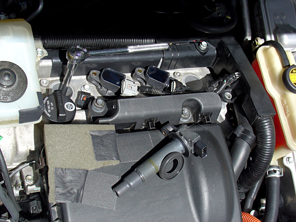
While the cowl is still out, it can't hurt to go after the spark plugs again --
inspection and real anti-seize this time.  They were done at 36K or so, but
only with a little oil on the threads.  They felt fairly dry again, but not
nearly as bad as the first time they came out.
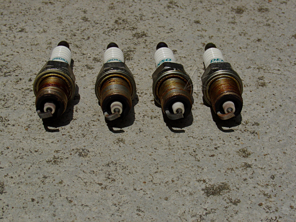
They still look pretty good.  A little bit of carbon on the #1 insulator,
nothing major.  Variation probably has more to do with how they sit in the
flow.  So I mixed them up to reinstall.

The reason this is relevant is that some engines actually take electrode
orientation into account, and require indexed plugs -- you use the one that
points the side electrode in a particular direction relative to the valves
when properly torqued in, and the head is marked with which plug goes in
what hole.  Fortunately the Prius doesn't deal with any of this, but there
could still certainly be some directional effects going on.
The ignitor doesn't clip around the plug contact; it just has a little
compression spring that bears down on top of it and transmits the zoobs.
Now, a lot of this basic fluid-change operation could have possibly been
short-circuited and all done from underneath using some sort of pump or
squeezie-thing to push the new fluid in through the level-check hole.  That
would have been the efficient, just-get-it-done method, and possibly somewhat
messier.  But the exploratory look inside and under the inverter is definitely
worth the time, as are the various other fixups around the engine bay.