A revised warm-air intake duct
Traditional thinking holds that an engine wants a *cold* air intake for a
denser cylinder charge and more power.  The Prius is no exception, with
its stock intake snorkel pulling air from over behind the headlight.  But
among the high-MPG-enthusiast community, there is plenty of precedent and
rationale for warm-air intake modifications to help with winter efficiency --
preheated air is less dense and needs less fuel thrown in with it for a
stoichiometric burn, and once you've made those excess BTUs that didn't go
into pushing the car, why not try to recover some of them?  Honda Insight
drivers especially use warm-air redirects to stay in lean-burn mode as much
as possible, since it is dependent on intake air temperature and can be very
difficult to attain in the winter.

The hose is two-inch "flexible preheat duct", available in 2-foot or so
lengths very inexpensively at most auto-parts stores.  It isn't intended
to be 100% permanent, given its very light construction, but forming up a
replacement piece every year or two isn't onerous.  It can bend tightly
enough to accomodate the turns in the path here, and holds its given shape
well.  The other component is adhesive-backed aluminum tape, used to shape
and reinforce parts of the run and seal gaps where needed.  Useful stuff.

While the previous year's quick-n-dirty warm-air hack did seem to raise the
intake temperature quite a bit above cold ambient, it was kind of clumsy and
rattly and I wasn't convinced that it worked as well as it should.  The A/B
test results from that also turned up no MPG difference in highway travel,
although having the warm-air intake on a Prius seems to help for a faster
warmup and overall MPG in general.  While examining the back of the engine and
exhaust header, I saw that not only is there a gap between the heat shield and
the head, there's a straight line between the two top heat-shield bolts upon
which I could probably piggyback a solid hold-down bracket of some sort.
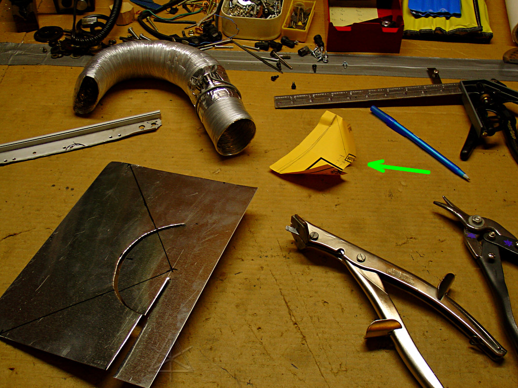
The bracket in question has already been fabbed, in fact, near upper left.
A very early attempt at making this newer method work had been by attaching
the slightly flattened hose end to said bracket, holding it in the general
back-of-head area and hoping it picks up enough air. But it evidently does
not, so some sort of spreader is needed to increase the pickup area along
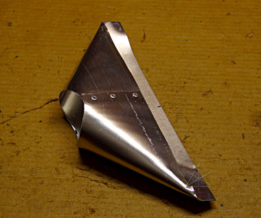
most of the slot. The piece of paper [green arrow] is the result of fiddling
with several different approaches to bending topology, from which it turns out
that a simple rectangle with a semicircle of sufficient circumference to wrap
completely around the 2.25-inch or so outer diameter of the hose will bend
around to form just the right sort of shape. Following the model, the real
thing is now being cut out of .025" aluminum sheet, which has enough stiffness
to hold its own shape.
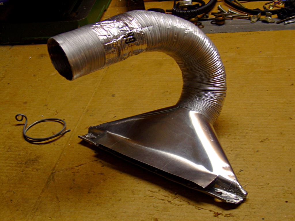
Next, the outer edges are brought around [using a piece of pipe as a mandrel
for smooth bends] and pop-riveted together.  The extra lip off the front will
become part of the mounting and bring the top edge closer to the engine head.
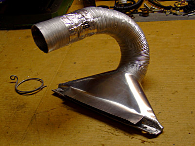
It's like, totally a vacuum-cleaner attachment.  At this point part of the
lip has become attachment points onto the bracket, and it's all pre-drilled
for the heat-shield bolts.  The aluminum tape reinforces the spot where the
spring-clip support helps steady the hose; it gets piggybacked onto one of
the harness-holddown bolts on top of the engine.

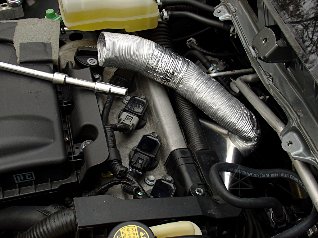
Back outside to the car, where the assembly gets bolted in.  The hose turns
out to need a slightly sharper bend than I anticipated to clear the firewall
and the A/C pipe, which looks nastier here than it really is -- but we're
still good, it's not restrictive.
A little early experimentation showed very little intake temp delta, so
something was clearly wrong.  A significant improvement comes from inserting
spacers about 0.2 inch high under the upper heat-shield mounting points to
widen the gap between its edge and the exhaust header bracket, allowing much
more air to emerge and get sucked up by the intake, as well as adding a
small baffle to prevent external air from coming in under the duct brace.
This pair of images shows the change in a less annoying fashion...  At
this point the stock bolts aren't quite long enough to reach through all of
that hardware and still thread into the bracket underneath!  Fortunately,
slightly longer ones were found in stock.

This simple change brings IAT deltas from only 20 degrees over ambient up to
more like 80 degrees.  The original theory is apparently fine, it just needs
a little tweaking.  The air temperature at the collector is probably even
more than that, and loses a certain proportion of heat as it travels over
toward the air box.
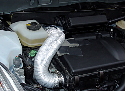
Here we've reattached the second half of the ducting, using a foam pad under
it to protect against abrasion on the air box.  It is slightly flattened
to fit under the hood, which sits fairly close above here.  The hose handily
clears the brake-fluid reservoir, the cowl, and the relay box.  The midway
joint is nothing fancy -- the front hose is slightly crimped down so it can
insert into the opening of the rear half, and the corrugations coupled with
placement seem to keep them joined fairly tightly.  No aluminum tape needed.
The join area sits just aft of the oil fill cap, making it easy to do oil
changes by simply removing the front half of the hose.  It may also get
removed to facilitate comparison tests between the warm-air intake and the
stock intake or just the open air-box fitting.  The old stock intake hose
end is simply pushed back behind the headlight and tied out of the way.

The main thing to watch for is this: anything that attaches to the engine
must move *with* the engine, or provide enough vibration damping between
the engine [that moves] and the surrounding frame and firewall [which don't].
That's why the fuel line takes that funny loop, and why the stock intake
hose has a ribbed flexible section -- all that is to accomodate the engine
shaking back and forth.  To easily see which parts move or don't, have the
car in Park with the parking brake off, and just push and pull to rock the
whole car against the parking pawl.  At the limits, the engine and transaxle
will be torqued against the rubber mounts by the wheels, and you can see the
motion thus caused.  It isn't much, but anything rubbing or abrading over
even a small range of motion can quickly wear through parts.

At this point, the cowl parts start getting reinstalled, reversing the
disassembly order from earlier.  A small touch of lube or anti-seize on bolt
threads eases reassembly and any subsequent removal.  The cowl bolts and the
wiper-link bolts should all be loosely installed before anything is torqued
down, to make sure everything lines up right.  And we must remember the funny
wiggle that the plastic cowl cover has to take to rest on the windshield
edge while also clipping underneath it.
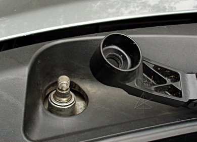
Realigning the wipers can be slightly tricky.  The arm bases and pivots have
splines to prevent the arm slipping on the pivot, but they're so finely cut
that it's easy to misalign them and then damage them by tightening down
point-to-point.  An easy way to correctly seat the splines is to loosely
finger-tighten the nut, and then wiggle the arm up and down the windshield
a little while gently continuing to screw the nut down.  This makes sure
the splines seat correctly.  If the wiper ends up in the wrong place, back
off and try the process again one spline's worth over.  Don't try to force
rotation to the next spline without loosening!

At this point, with a block-heater, revised WAI, and new tires, we would
think we're *totally* ready for winter.  But wait, there's more!  How about
all that extra heat that just flies out of the engine compartment on a cold
day?  See page four for the final step of configurable grille-blocking.
_H* 061116