
Warmer days have finally arrived in the northeast, bringing with them the
rumbling of glasspacks in the distance, the lure of the road, and digging my
collection of backprobe-pins out from where they've been stored over the
winter.  After what has seemed like interminably persistent chilly weather,
it's finally getting to be time once again to poke around under the dash in
the Prius, and take the scope and meters out cruisin' on a Saturday night.
Some of us are weird that way.

So as a simple spring data-observation project I've been watching the "VH"
lead in my '04, named "inverter condenser voltage monitor" in the manuals or,
amusingly, "Voltage after raising pressure" in the spec that Toyota gives the
scantool manufacturers.  Okay, we do speak of voltage as "electrical pressure"
sometimes.  VH is the indication back to the hybrid ECU of how high that
post-boost rail voltage is across the caps and power-transistor rack feeding
the two motor-generators.

The sensor is a 5V powered circuit from inside the inverter control
electronics, and sends a very solid low-impedance signal back from the
inverter to the ECU -- a 5K bypass load to ground didn't touch its level in
the slightest, so it's probably one of those typical 100-ish ohm op-amp
outputs.  I simply brought it up to the spare input on my panel voltmeter,
which is the old Rat Shack analog cheapie that has about 15K in series.

VH reads about half a volt in IG-ON with the hybrid battery not yet connected,
and once the car is fully powered up the sensing circuit receives the baseline
battery voltage -- usually about 220 volts in real life, which corresponds to
a VH reading of 1.9 volts or so.  At highway speed and full boost conditions,
it reached a maximum of 3.6V to indicate 500 volts at the motor rails.  The
manual gives its nominal "good" range in READY mode as 1.6V - 3.8V, which
gives it a couple tenths of diagnostic slop outside the real-life range.
The hybrid ECU knows how to translate this into a real rail voltage figure,
which can also be queried via OBDII with an appropriately capable scantool.

Watching VH on an analog meter is instructive; the rail voltage can rise and
fall very rapidly despite the big capacitors.  The motors can suck those down
in an eyeblink, of course.  In general, the rail voltage starts to rise above
the baseline under two operating conditions:

	*  when any motor's generated EMF would be above 200V

	*  when we need to send charge current to the battery

The first condition depends on RPM of MG1 or MG2, which of course can vary all
over the map, and the second is a given since without a voltage source higher
than the battery terminals, you can't charge the battery.  The second condition
is also special in that voltage rise doesn't come from having boosted the
*battery* voltage, since we can't draw from the battery while charging it; the
rise comes from having boosted generation output from at least one of the
*motors*.  This is a known mode of operation.

There is some study of boost voltage given in report ORNL/TM-2006/423 aka
890029.pdf [see my linkfarm for a pointer if you haven't avidly read through
it already], including data collected from several drive cycles, but much of
what Oakridge observed about VH was left as "indeterminate".  What's useful
here from that paper starts on about its page 15 -- the tables and charts of
generated EMF from both motors -- some by direct measurement and some by
extrapolation, but it's clear that voltage outputs of either MG correspond
quite linearly to RPM:
For ease in determining some theoretical thresholds during vehicle operation,
I've taken Graham Davies' classic nomograph, flipped it on its side, and added
a voltage scale.  The thin orange and blue lines show approximately the same
data for MG1 and MG2 generated voltage, peak and RMS, mapped onto the existing
RPM scale.  Now we have a quick reference chart, upon which we can draw the
usual straight line across the nomograph for a given operating condition, note
the RPM of MG1 and MG2, and determine the EMF that they should be producing
at the time.
The vehicle speed on this chart is little off for the '04+ Prius since it was
charted for the slightly different final drive ratio and tire size of the
Classic.  But it is close enough to be useful here.  Vehicle speed relative to
MG2 RPM will always vary based on tire type and inflation anyway, so it's
almost impossible to have an exact quantifiable correspondence there.

What is interesting to note is that where the engine-off speed ratio of MG1
and MG2 through the planetary is about 2.6 : 1, the generated EMF capability
ratio is almost the exact inverse.  Thus if we determine an ICE-off coasting
RPM pair and then look at the respective voltages of each MG, we see them
coming up as almost equal -- for example, at 34 miles per hour we have MG2 at
2000 RPM and MG1 singin' away at 5000 RPM in the other direction, and both
trying to produce somewhere north of 250 peak volts with MG2 winning out by a
narrow margin.  That inverse matching relationship seems fairly consistent
across the whole range of speeds.  Almost like it was designed that way, huh?

The other interesting aspect is that as the generated voltage becomes higher,
the boosted rails would have to rise to a higher voltage to "stay outside"
the envelope naturally produced by the motors and diodes.  This could either
come from the voltage crests produced by either motor in the same manner as
an alternator, or be deliberately kept even higher than that by the boost
circuit.  As vehicle speed increases and VH is observed, it appears that
the latter situation happens but in a seemingly inconsistent and somewhat
nonlinear manner.

So an obvious first test is to explore that.  What happens if we just coast
down a big hill in Neutral with the engine off?  The scantool can query and
record RPM and voltage data, so armed with that I headed off to my favorite
downhill test track run -- Route 2 down into Alewife.  Late at night it's
lightly traveled enough that it's quite feasible to crest the top at 20 MPH
with the flashers on, engine off, and the car in neutral, and then let gravity
take over.
I peaked at around 63 MPH, and was able to slow-roll off an exit without any
interference and keep drifting along all the way to the T station.  This
shows a definite VH jump, but not quite where I would have expected.  At
2000 RPM, according to the Oakridge data, MG2 would already be producing a
peak voltage higher than the battery -- and yet the the rails don't seem to
kick up above that until a little later on.

I soon realized that simply watching VH wasn't enough, and I also needed to
watch the control input to the boost circuit to try and see what was being
sent to the buck/boost converter at the same time.  There are two more signals
of interest: CPWM and CSDN, for converter PWM and shutdown respectively, which
are easily accessed at the hybrid ECU.  Here's what the relatively simple test
environment looked like, and in this case I went to the trouble of labeling
the pinned-out leads because I was about to head off for another Earth-fest
type event, and I figured leaving a bunch of test gear in the footwell would
make a nice "rolling laboratory" type demo to show people.
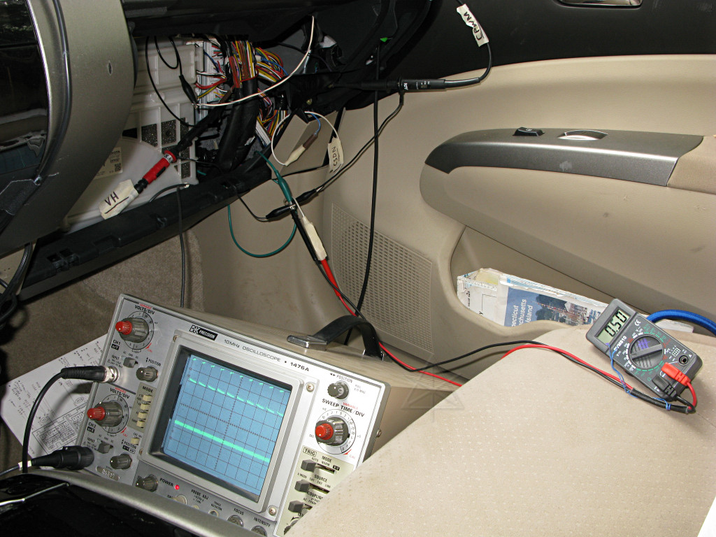
The scope is showing VH below and CPWM up top [select the pic for a larger
view], and CSDN simply goes over to the multimeter.  VH seems rather noisy
once the whole system gets fired up, whether the boost converter is running
or not, but the ECU reading it apparently doesn't mind that.

CSDN can be pretty much eliminated right away, since it seems to go from 9.6
volts at IG-ON down to 0.5 when the car goes to READY mode and never varies
away from that.  This is different from the inverter MSDN/GSDN shutdown leads
which actually do get used as gates to force the motor inverters to a totally
disabled state while in Neutral.  Not so with the boost converter -- it seems
to be always enabled, but the CPWM signal itself only comes on intermittently
and by default stays low as long as VH is indicating a 220V baseline.  And
since there's only the one PWM lead, that means one or the other transistor
of the boost converter switch is on at any given time, similar to how the
inverter "U" leads fan out to their respective high/low transistor pairs on
the motor phases.

Let's quickly review the boost converter circuit, highlighted here:
We can only conclude that with the CPWM signal held low, that the upper
transistor must be on since leaving the lower transistor on would create an
immediate short across the battery once the inductor saturated.  The default
state with the upper transistor held on is harmless, and effectively just
connects the battery to the motor rails bidirectionally which is a safe
state.  Each high pulse of CPWM must therefore turn on the lower transistor
instead and create that almost short-circuit situation, except that the
current is used to build a field in the big inductor [aka "reactor"] for
a brief time before usefully dumping it to create the boost voltage spikes.

CPWM runs at right about 20 KHz, varying its duty cycle to pass more or less
energy through the inductor.  I don't think I saw it ever get to more than 75%
on-time, though, and only in very brief transients during highway-speed
accelerator movements.  Usually it stayed down around 50-60 percent on the
highway, dropping off to maybe 20% before ceasing entirely as speed decreased.

So, back to that mystery about the downhill-run test and the scantool data.
The rail voltage rises fairly abruptly and at an unexpectly high RPM.  Just shy
of the aforementioned 2000/5000 RPM combination, the peak voltage of either MG
should already be well above 220 volts.  With the inverter rack disabled and no
battery current either way, i.e. the definition of Neutral for the car, leg-to-
leg peak voltage would get rectified out through the diodes and raise the
capacitor voltage in a relatively uncontrolled way.  [This is one major reason
you shouldn't flat-tow the car.]  With only the motor windings and diodes in
play like that, the rail voltage should begin following the rising curve around
1500/4000 RPM, and yet it isn't until closer to 2000/5000 that we see CPWM
become active and a sudden jump in VH.  Where is it all going in between?
Battery current doesn't visibly change away from the almost-zero of running the
DC/DC, so I have no explanation for this.  It is clear that the system does try
to keep VH out of the way of the peaks eventually, but not quite where expected
in the free-rolling case.  Either that or Oakridge got the peak-to-RMS ratio
wrong and it could be lower than indicated.  They claim it's not a sinewave,
but peakier than that.  Perhaps there's just not enough energy in the very tops
of the peaks to really matter.

But that's not all -- a related mystery is that with MG2 pushing past 3500
RPM, its peak voltage should actually exceed 500.  And yet VH remains dead-flat
across the whole span of my higher speed, and with Neutral keeping the inverter
from affecting the motor windings, again, where's the excess going?  This
scenario could be a whole lot worse -- it is easy enough to pop the car into
Neutral when driving at even higher speeds [with the engine running, but MG2
would still be spinning very fast] so what happens when its generated voltage
would be pushing past 600?  The *capacitors* are only rated for 600, but the
top speed of the car could push motor voltage way past that.  This is what
gives rise to the discussion of field weakening in the ORNL paper, but that
assumes that their outboard system would always have control of the inverter.
How about when it doesn't?

The only way to get these answers is probably to start looking at the IGBT
gates themselves, to see if the inverter ever "cheats" and temporarily ignores
the SDN leads to protect itself.  I've observed that the U/V/W drive signals
from the ECU never stop running and modulating to follow the motor around based
on resolver position feedback, even with the car in Neutral.  In other words,
the three inverter control leads always act *as though* they were tracking the
generated envelope whether the motor is really handling any power or not.
Perhaps the ECU is still giving the inverter a way to perform that field
control if needed?  This still remains to be explored.  I do know conclusively
that the engine is not spun in this state, even when MG1 hits the theoretical
10,000 RPM point on a screaming warp-neutral dive, and the state of the engine
doesn't matter anyway when MG2 output is considered.
Besides the downhill run detailed above, here are some other operational
observations about VH.

Doing an engine run-up by pressing the accelerator while in Park brings the
system to full boost at 500V if the run-up enters the 2400 RPM region.  MG1
turns at about 9000 RPM during that event and gets well into the boost range.
For those who were worried about MG1 spinning faster than 6500 RPM back in
the day -- guess what, your Classic does this too.

Force-charging at any greater than 20 amps seems to start bringing boost in,
but at a fairly low duty cycle unless you really stand on it and ask for more
like 50 amps.  EV mode or reverse against a set parking brake or a steep hill
can request quite a bit of current at very low speed or even a standstill.  At
around 40 amps of draw from the battery, CPWM starts kicking on.

A normal takeoff from a standing start, engine running, yields a bit of boost
voltage because MG1 has to turn fairly fast to let the engine come up to the
desired RPM with vehicle speed still low.  As the car accelerates past about
15 MPH, this reduces back to the base voltage for a while until speed gets
above 30 MPH or so -- because as the ring and carrier spin together, MG1
doesn't need to turn that fast and often reverses through 0 in that region.
Boost begins around the same MG2 RPM point as during the neutral roll --
low thirties MPH.

Interesting things happen in the 30 - 40 MPH region, especially in EV mode.
I know from some other observations that the inverter drive signals for MG2
move from a multiple-kilohertz PWM regime into simply switching 3-phase square
waves at the motor's native electrical rotation speed, because it's more
efficient and the motor is turning fast enough to smooth out any torque ripple
that would produce.  But overall applied motor current can still be regulated
smoothly!  How?  By using a variable boost voltage.  In this speed range I see
VH rising and falling corresponding to my go-pedal demand, with its lowest
baseline creeping up a bit as I head toward 40 MPH and MG2's own peak output
rises sufficiently.  It's almost like having the switching behave like a
brush commutator, simply leading the electrical rotation angle by 60 or more
degrees, and regulating motor speed via applied voltage like it was a big ol'
toy-train rheostat.

The other really interesting scenario is regen braking.  In almost all cases
over a wide range of speeds, VH increases corresponding with regen charge
current.  However, that voltage couldn't be coming from the boost converter,
since during regen it's acting as a BUCK converter to regulate battery charge
current.  Instead, the boosted rail voltage comes from the MG2 as its own
windings get used as the boost circuit at speeds where its native output could
never get over the rails without help.  I can produce a VH rise with a quick
little stab of the brake pedal all the way down to 9 or 10 MPH -- accompanied
by that same little high-pitched whine that tells my ear-dyno that it's
working.  It is still somewhat strange that the boost circuit's top transistor
isn't simply left on and motor modulation used to regulate charge current [like
the Classic Prius would have to, lacking a boost circuit!], but maybe there's
an efficiency gain from letting the motor rails ride higher and using the
buck/boost circuit.  It may also just be done to prevent the inductor from
saturating.

In general, the boost circuit seems to go active any time the system needs to
handle serious current through the motors, in either direction, and stay in
a default state during lighter load conditions at lower speeds.  Some of the
transition regions really are somewhat erratic, as ORNL noted, but it should
all be explainable in the long run.  It may just require having some extra
scary wires hanging out of the inverter.