|
Modifications would certainly involve taking apart various covers
and trim to access the wiring needed, so investigation of that proceeded
during the first big bottom-to-top charge.
As long as the wiring itself remained connected while charging was going
on, there was still no harm in displacing a little plastic, and then
the serious track-down of electrical stuff could happen later.
Besides, just going into this I didn't have the necessary documentation
yet.
For those thinking "but geez, you're gonna totally void your warranty a week into ownership!" ... two words: Magnuson-Moss. Google it. |
|
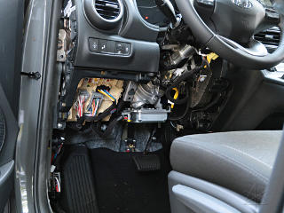
As I began adventuring around the dash I did not know at first which of the many connector blocks I'd need to tap in near to add my mods. It was still useful to pull interior trim and see where they all were, because then I could start relating their locations to the service information. To obtain that I signed up for a Techinfo subscription and began pulling down schematics and connector lists so I'd actually know what I was looking at here. |
|
For making mods of any sort, there are three critical aspects of knowledge
needed about any given car.
The overall schematic, to see how a subsystem is designed and wired in;
the connector diagrams with pin numbers and wire colors and hopefully
descriptions of each pin along with; and then the *location* of each
relevant connector.
Once I got onto Techinfo I pretty much knew what to look for, and while it
was a bit more tedious than "wget"ting a bunch of PDFs like back in the Prius
days and thus less complete, I downloaded a bunch of helpful stuff.
Interestingly, Hyundai's service info calls part and connector locations
out on *photographs* of partially disassembled cars, rather than the line
drawings used in the Prius docs.
Not sure which is more clear, really.
Once the "big recharge" was done I could freely work on the wiring itself, and the next few days held quite a bit of exploring. | |
|
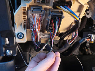
It didn't take long to learn what powers the daytime running lights and
what connector their wires come out of.
I broke out my set of tiny connector-lug tools and simply backed the two
relevant sockets out of the block and taped them back out of the way.
The bigger connectors here have built-in self-ejector levers, which helps avoid having to pull on any wiring. |
| The large beige structure is called the "integrated gateway and power module", and is Hyundai's variant of what the automotive industry calls a "smart junction block" or SJB these days. In effect, the Prius body ECU is also one of these, embedding control electronics, relays, power distribution, and fuseholders all into one honkin' module. | |
|
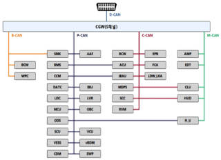
In the Kona it's gotten even more complex, with the "gateway" function also serving to route between at least four CANbus networks. This is the overall network diagram for the Kona, kindly provided by a somewhat mysterious researcher called JejuSoul, who I'm guessing is Korean and has contributed a lot of interesting OBD-2 and data-extraction information for several Hyundai/Kia vehicles to the community. [That is more deeply explored in the "data" section.] Not only does the gateway relay to the four major operational networks, many ECUs are also dual-homed onto more than one network themselves. Cars bear a striking resemblance to commercial data centers these days, and it's likely that the gateway also has functionality to firewall off some networks and modules from each other and only pass certain types of needed packets. |
|
Another
technical take on this
and a module glossary can be found on a possibly-unofficial service info
site called "hkona", although that's geared toward the gas Kona rather
than the EV.
The body electrics across both models are pretty similar.
Note carefully that the car's J1962 diagnostic connector brings nothing but a tiny stub network out from the gateway. It physically runs all of about six inches to the IGPM, in fact. Not only does every diagnostic query to any ECU in the car have to get brokered by the gateway module, it's impossible to just plug into that and passively "listen to the bus" like in the Prius that has only one network. Serious CAN debugging/reverse-engineering would need deeper digging around and modding in direct taps into some of the other networks instead. The folks over at EVTV Motor Verks had to do this to even get started on many Teslas, which don't have any standard diagnostic connector at all. | |
|
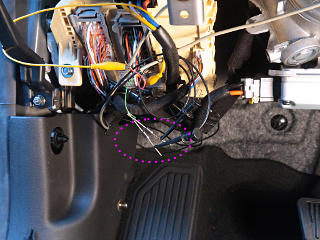
Specifically, the clip was part of a quick and totally redneck test of Yuppie Button basics, with two diodes hanging in space feeding a couple of brake-light lines as proof of concept. The Button is fully described in its own section, but it's worth noting that almost everything I'd ultimately need to do for it would happen right here at the main junction/fuse block rather than down at the front-to-back harness connectors behind the kick panel. At this point the physical button was in and nominally usable on a test basis, and as sketchy as that lashup was, it was a nice exhibit to show geeky folks at a social gathering that weekend. "Yes, I've only had the car for a few days"... |
_H* 190929