Ironically, this could also plug straight into the plug-out inverter in the Prius and utilize both legs of it, as long as charging demand was limited to less than 10 amps.
| I began thinking about the home-charging aspect and looking into some options. Not only is it kind of a cool concept to have your own "gas pump" right there at home and maybe your workplace too, there's helpful gear that can be taken on the road and adapted to many different situations. Everything sort of gelled very quickly in my mind, a clear picture of what I would need to do and need to procure. I would need an EVSE, the glorified relay box that feeds AC power to the car once all the safety interlocks are in place, and a way to feed fairly massive power out to that. A charging setup doesn't have to be bolted to the wall of a garage; only the proper sort of outlet needs to be there. To that end I made sure to select and order an EVSE with an input plug, rather than one intended to be hardwired. I would consider it to be a portable unit, that could charge the car anywhere a suitable feed could be found or created. |

|
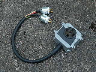
A very common high-current plug/outlet type used in EV charging is the NEMA 14-50, often found behind electric stoves and in hotel ballrooms. It was kind of amusing that I already had some 14-50 hardware sitting around the house for some time, perhaps with the idea that I *might* get into some EV stuff one day. I also had a bunch of heavy cable squirreled away in "the hoard", some of which had been used for power distribution back in the laser-show days. It wasn't a big step to put together my first piece of EVSE-related equipment, even before any of the real gear arrived -- my version of a "combiner" to create a 240V outlet from a pair of ordinary 120VAC household outlets. |
|
Obviously the feeds have to come from different legs of the panel and NOT be
the GFI type, as the neutral lead is never used in a 240V charging setup.
[For completeness, however, one side's neutral on this does get run to the
outlet's neutral lug.]
With good heavy spec-grade extension cords run to the inputs,
in theory this could safely provide up to 16A and 3600 watts
without modifying the existing electrics in a home.
I figured it would be a potentially useful "destination charging" travel
adapter.
Ironically, this could also plug straight into the plug-out inverter in the Prius and utilize both legs of it, as long as charging demand was limited to less than 10 amps. | |
|
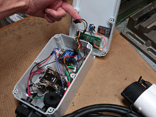
Soon enough the big Amazon order showed up, including the GoPlug 40 that I'd chosen. This is the pre-built version of the OpenEVSE unit, and ordinarily I might have gone for the OpenEVSE kit but this one would not only save me a little time, it had a significant difference in the way it handled wi-fi. Rather than the traditional setup where the EVSE would join an existing home network and then start spewing data to "the cloud", the GoPlug offered the option of simply running as its own self-contained access point and mini-webserver. I didn't even need that much initially, so on a brief tour of the innards I simply disabled the wi-fi board entirely. All of the necessary configuration can be done with the single-button interface and display on the front. Really, all I could see the wireless aspect being useful for later on might be checking on charge status from indoor comfort. Maybe not "from anywhere" as so touted about cloud-based IoT stuff, but who cares when the device in question is all of 20 feet away? |
|
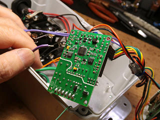
The meat of the control board is on the underside, where the top is mostly taken up by the +12/-12 power brick. Popping the purple pilot wire off made it easier to turn over. The pilot was of particular interest because I was about to bring a tap from it to the exterior, so I could scope it and watch the protocol. |
|
In a bit of commentary exchange with the GoPlug support I mentioned that
the pilot wire seemed very short with no service-loop slack, and they replied
that it was intentionally done that way.
Part of the spec on how EVSEs are built includes that on an accidental
pull-out of the charging cable, the pilot MUST be the first thing to break so
that charging stops and the cable is de-energized before the rest of it gets
ripped apart.
I was highly amused that someone thought about this "what-if", but perhaps
it was one of those lessons learned from bitter experience?
I shifted the whole output cable about a half-inch inward through the gland anyway, just to give myself a little more working room. Didn't violate the spec, it just made things easier to get back together. | |
|
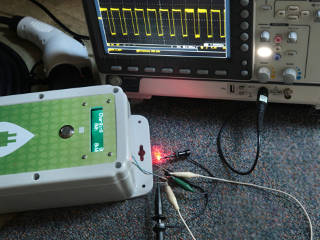
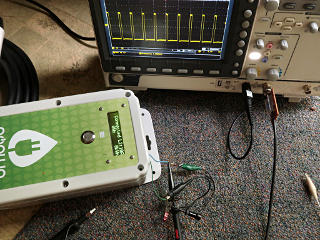
I brought the pilot and a ground wire out over the edge of the case, with the cover just loosely screwed on to leave a gap. A handful of parts clipped together was enough to power up the unit and simulate a car asking for charge -- the J1772 spec is quite simple, using only a diode and a couple of resistors as an interlock to enable energizing the output. I used an LED instead, whose forward voltage drop actually made it easier to use stock-value resistors for the fake car-side network. Here we see the 1KHz pilot squarewave with its upper voltage level appropriately reduced, and the duty cycle from the EVSE telling the car it could draw up to a full 40 amps if it wanted to. With the second resistor bridged in, the big relay in the GoPlug clacked on and it went into "charging" mode. |
|
Here's the EVSE configured to only deliver 10 amps; much shorter duty cycle. It's up to the car's on-board charger [OBC] to obey this and up to the user to configure the current to match the supply capability; usually the only penalty for getting it wrong is a tripped breaker. A real 14-50 feed would generally be no problem, but current would have to be reduced before, say, using the combiner on a pair of 20-amp outlets. The general wisdom is limit to 80% of the breaker rating, as it's a steady-state draw over a long time and stuff *will* inevitably get a little warm under such usage. |
|
I have heard Level 2 control pilot protocol referred to as the "NTSC of
charging interface specs", combining multiple aspects of signaling and
safety checks into one wire with a relatively simple analog method.
Protocols for higher power charging go way beyond that and get far more
digital and complex; this is explored in the "rapid charge" section later.
At this point I didn't have the car quite yet, but I left the tap wires in place and would look at the pilot again during a "real charge" later. The protocol and supporting electronics are described in a fair bit of depth in a slide deck [PDF, 3.8 Mb] from the OpenEVSE folks, which includes some horror-story pictures from early development. It is interesting that the spec allows using the AC safety ground as the reference for the pilot signal. There must be some cases where a really noisy ground could mess with it enough to prevent proper operation. Or the ground may be completely missing in other setups -- this becomes relevant in the "charger games" segment later. | |
|
|
|
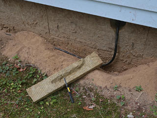
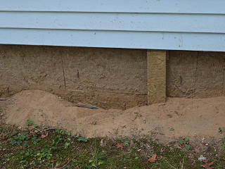
Installing the feed to the driveway actually happened the day after
picking up the car, but is most appropriately placed in this section.
With a
superinsulated house
one does not just go randomly banging holes through the wall, but I'd made
a special provision for passing cables or hoses to the outside without
compromising the envelope.
The logical place for my cable to emerge was the "magic hole", a short bit of
PVC conduit mounted through a special panel with removable end caps.
This would be a semi-permanent installation but could be temporarily
backpulled if needed later.
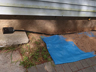
The cable is 8/3 type S, which is ample gauge for the 30 amps the car would draw, and is entirely suited for direct burial similar to UF Romex. I decided to shallowly trench it in around the corner of the house to make its presence less obvious, and constructed a little fitted Roxul cover to sort of stealth in its exterior drop from hole to dirt -- modulo the obvious color difference between fresh material and stuff that endured outdoor abuse for five years! The soil all the way along here to the endpoint is always so dry anyway that it never packs down, so consistently arid that ant-lion pits appear in it every summer. | |
|
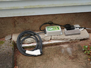
Near-term, the outlet box could simply sit on the slab-let of concrete, with some kind of weather-resistant cover when not in use. [Ahem, plastic bag...] Normally the EVSE itself would be unplugged and kept inside the house or car, and I was already considering options for building some kind of weather-protective enclosure over this. |
|
|
|
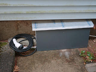
On nice days/nights the EVSE could just sit out during charging, since it's
a fairly tightly-closed box to begin with, but later on I did put together
a semi-quick-n-dirty hutch to drop over everything when needed.
It simply leans against the house wall.
The main problem with leaving things outside is all the natural detritus
and spiderwebs that accumulate, not to mention more rapid oxidation of
electrical connections in the humidity.
Kept indoors or out or in a garage, this is why an occasional shot of De-Oxit on various plugs should be part of anyone's home EV infrastructure maintenance. It can't hurt to have some handy on the road too, to clean up public chargers that might need some attention. | |
_H* 191002, updated 200928