|
| [Note: this is not a product or kit. It is part of a strictly one-off series of analog Prius instrumentation, documented as a model for those who would want to build [and likely improve upon] the original design.] |
For some obscure reason, Toyota does not provide an engine or coolant
temperature gauge visible to the driver of a Prius.  However, a sensor for
it is certainly installed, and coolant temp is one important input factor
in many decisions made by the computers.  Different functional states in
the hybrid system are entered as the ICE warms up and cools down.  However,
knowing how warm the engine is can give the *driver* a better expectation
of how the car will behave, as well as a better view into how temperature
and heat loss may be affecting fuel economy.  So it seems useful to add
some sort of readout, and then document it in a somewhat overkill web page.
Engine temperature in the Prius [and probably most other modern cars]
is read from the coolant passing a particular point in the cylinder head,
via a negative-temperature-coefficient thermistor device in contact with
the glycol flow.  The thermistor is fed from a bias circuit with a fixed
resistor of about 2500 ohms, powered by a +5V rail internally generated
by the ECM for the engine.  There are actually several thermistors used
around the car -- one for intake-air temperature in the throttle body
throat, one for outside ambient temperature hung in front of the radiator,
another in the coolant-storage thermos bottle, probably a couple more
related to cabin-air temp control, etc.
As thermistor temperature rises, its resistance goes down and thus the
voltage read from the junction at "THW" falls as well.  The problem is that
the response of the thermistor is very non-linear, changing its resistance
much more per degree at colder temperatures than when it is warm.  Note
that not only does the resistance follow a characteristic curve, its scale
on the left is *logarithmic*, indicating that resistance variation is even
wider than it looks at low temperatures.  Adding the fixed series resistor
helps flatten this out a little bit, especially through the region of real
interest, but it's still not feasible to track with a straightforward gauge.
The span in question is from a reasonable range of outdoor ambient up to
slightly above the normal running temperature of the engine when the
radiator thermostat starts opening [about 180 F or 82 C].

The standard way of dealing with this is to read the sensor voltage through
an A/D converter and let the computer simply index it into a lookup table
and do a little curve-fitting to determine the temperature.  The car's
ECM does this, and that value can then be queried and read via OBDII.  A
number of Prius drivers are already out there happily reading their engine
temperature with a ScanGauge or CANView or similar products.  However, the
overall development of my particular instrumentation block has been in the
analog domain so far, directly tapping certain sensor and control leads and
displaying their states appropriately.  The gauge cluster includes a generic
0 - 15 voltmeter, useful for monitoring not only the 12V bus but also
displaying any other voltage value of interest.  Therefore, the challenge
is to convert the thermistor output into a linear voltage, giving a rough
representation of temperature value over a range that maps reasonably well
into what the meter displays.  This conveniently turns out to be 0 - 10 volts
to indicate 0 - 100 degrees C.
First step, of course, is to find the appropriate line.  It's the THW lead,
initially tapped by the traditional paper-clip jammed in next to the lug and
brought up atop the dash to the "temporary" breadboard [that had been riding
around in the car the entire summer, ahem].
Direct voltmeter readings could then be correlated against the ECT data
read from an OBDII scan tool.  This little table was made just by watching
a warmup cycle and scribbling numbers and then roughly graphing it, although
in the warmer weather at the time I couldn't get lower than 20 C.  Then
Ken@Japan was kind enough to post his "official" table:

  VOLT  __ degree C
   4.09 __ 0
   3.64 __ 5
   3.22 __10
   2.78 __15
   2.46 __20
   2.18 __25
   1.88 __30
   1.67 __35
   1.48 __40
   1.31 __45
   1.15 __50
   1.01 __55
   0.88 __60
   0.77 __65
   0.68 __70
   0.60 __75
   0.53 __80
   0.47 __85
   0.41 __90
   0.36 __95
   0.32 __100

Either way, that annoying nonlinearity is still there.  Ignoring that for
the time being, the logical next step was to drop a simple 10x voltage gain
op-amp circuit onto the proto-board to see part of the raw thermistor output
range on the meter, which would top out at 11V or so [aka 50 C or cooler]
but at least display the high end of the range of interest.  It would sink
down to just about 5V [aka .5V at the thermistor] as the engine fully warmed
up.  Armed with that simple follower and the little graph above I could have
easily remembered a couple of arbitrary critical points and gone on with life,
but I figured it would be much nicer to follow through on the use-the-voltmeter
idea and convert to degrees C somehow.  Doing that would also give me greater
display range, from zero C [freezing] to 100 C [when the radiator fans come on
and you might want to become concerned about overheating].  I wanted to at
least *try* for such a circuit before permanently building anything onto the
component board behind the gauge panel.

After groping around the net for thermistor-conditioning circuit examples
and reading up on logarithmic amplifiers in Horowitz & Hill, I realized
that I needed something like that -- something with nonlinear elements in
the feedback path but customized for the voltages in question.  I noodled
a couple of gain structures and dug around in the junkbox stock of Zener
diodes to see what I had, and figured I could obtain reasonable enough
accuracy with two inflection points of gain-slope change to approximate
the curve.  Obviously some part of it would have to be an inverting amp,
so that output voltage would increase as the thermistor voltage came down.
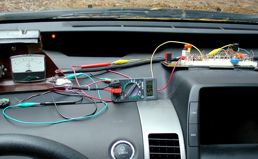
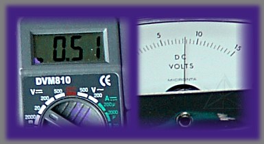
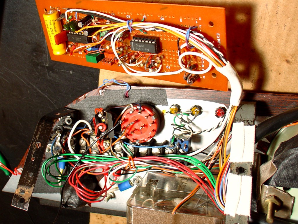
After some initial testing on the bench, it was back to wires-all-over-the-
dash mode.  I could fake the thermistor voltage input with a pot [the blue
frob near the right side of the protoboard] to fine-tune the circuit response.
That's how I'm getting readings here despite the car not being powered on!
Then I could power up the HV system and the OBDII scanner and see how close
I was getting.  I realized that I could also carefully bias the thermistor
input itself, and cause changes in the OBDII readings without the engine
temp itself needing to rise.  Here we see a nice correspondence between .5V
and a little over 80 deg C, which is about right for normal steady-state
running temperature.
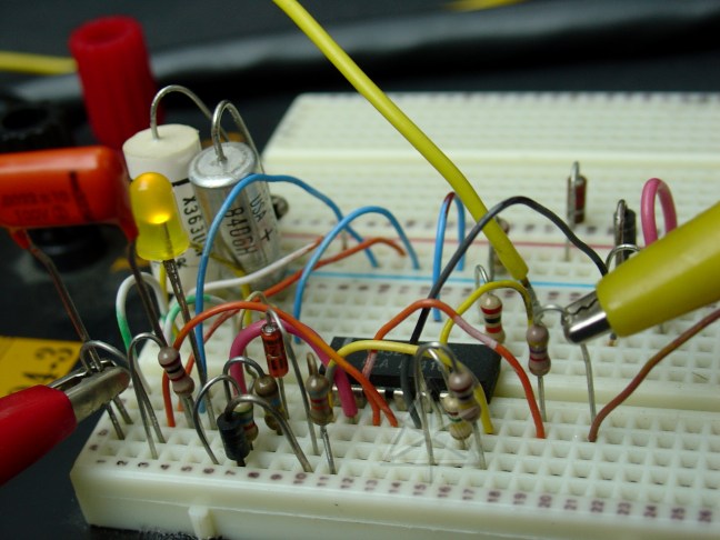
The bulk of trial-and-error happened right here, in the little nest of zener
diodes and resistors.  The end result?  A circuit that works fairly well,
described below.  The best way to refine the accuracy, frankly, was to just
screw around with resistor values until it worked.  I have no idea what the
transfer function of this thing is by now, and it's just not worth trying
to do the math.  Besides, the zener diodes don't exhibit sharp transitions
at the inflection points -- a side effect which actually helps make the
circuit's response curve much smoother and more accurate.  It gets slightly
weird near the 0 and 100 endpoints, but otherwise it's within about 10
degrees over the whole range.  Certainly good enough to commit to a permanent
circuit, considering that it's driving a cheap Rat Shack analog voltmeter.
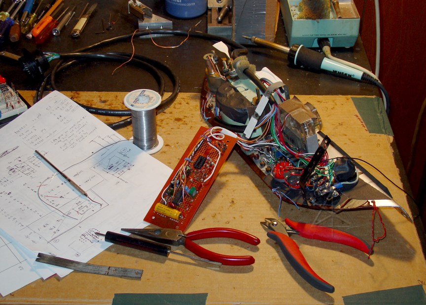
This was the last hack to go into the first round of Prius instrumentation,
and it was time to add it into the gauge panel for real and button the whole
thing up for the winter season.  So not only did the working circuit get
transferred to the little circuit board here, the wiring behind it was
neatened up a bit and the proto-board taken out of the car for the moment.
And the THW tap was de-paper-clipped and made permanent via the usual
slit/solder attachment, with a lead through the Big Connector up to the panel.
In fact, at first I tapped the wrong ECU wire [which is also white and right
next to THW, dammit] and wound up reading IAT instead.  I left that in
for a day or two to better see the effects of the warm-air intake mod
[see http://techno-fandom.org/~hobbit/cars/warmair/], and then finally
moved it to THW and dressed up the harnesses behind the glovebox.

This whole gauge effort is definitely a one-off prototype, since many of the
parts [including the panel itself!] are reclaimed from 20-year-old projects
in long-past vehicles.  Reuse, recycle!
The circuit board holds the electronics to support the injector-monitor
light, the current meter, the brake-pressure monitor, and now the temp gauge.
It bolts onto the steel packing-strap braces on the rear of the panel.
The big red rotary switch is the selector for what the voltmeter shows,
and yes, it's a break-before-make type.  There's still a little real estate
left on the board, two unused op-amps, and more inputs to the switch, so I
might come up with something else to monitor later on.  Fuel injector duty
cycle, perhaps?

Gotta love those LM324 op-amps.  Their inputs are valid to or even below
the negative rail, so they're perfect for ground-referenced single-supply
conversion circuits like this.
Most resistor values were determined experimentally, and results from trying
to duplicate this exact circuit may vary due to resistor tolerances, zener
characteristics, etc.  Starting at the second op-amp and working backward,
R7 and R8 yield an inverting amp with a gain of 1.5x, sufficient to take a
certain range of intermediate voltage (Vi) and span an output from the
negative rail to near +12V while "seesawing" it about the 5.1V reference
from Z1.  This provides output over the desired range, 0 - 11ish volts.
It is also preferable to do the inverting stage in the second amp, to avoid
bringing the thermistor tap into a "virtual ground" point which would probably
have less input impedance and possibly interfere with the signal to the ECU.
But even with the much higher input impedance in the + side of the first amp,
a nominal protection resistor is used in case something goes awry.  Vi is the
"linearized" output from the thermistor, and must be constrained in such a
way that the zener diodes determine appropriate transition points over its
range.  At high temperatures, resistance is low and delta per degree is low,
so the gain of the first op-amp must be at its highest -- in this case,
perhaps 8 or 9.  This is its "base state" with little or no current through
the zeners.  As temperature heads lower, thermistor voltage rises and the
difference between the amp output and its negative input begins to crest the
3.3V threshold of the first zener stage, bringing the parallel R4 into the
feedback path and changing the gain toward 4 or 5.  This changeover is not
sharp, in fact -- it happens over a volt or more of output delta, and as
temperature falls further still the circuit transitions fairly smoothly into
its third gain-mode with the 5.1V zener now in play too.  Final gain, when
thermistor voltage is around 3.5 or 4 volts near freezing, is less than 2x.
At that point it's irrelevant since the inverting amp is producing 0V and
we simply accept the limitation that temperatures lower than 0 C cannot be
displayed.  The engine spends relatively little time at such temperatures
when running anyway.

One of the most fun things about this is watching the head temperature
bounce upward as the stored coolant is pumped back in from the thermos
bottle at startup.  If the engine is prevented from starting [by shifting
to Neutral or hitting the EV button], it is obvious that the recovered heat
rapidly dissipates into the rest of the block.  So it is actually best to
let the engine start when it wants to, right after the pump cycle when the
*cylinders* are maximally preheated -- emissions are likely to be lower as
a result.  Continued warmup will heat the rest of the block anyway.

It's also somewhat scary to see just how much cabin heating robs from the
engine.  It's not a particularly massive block in the first place, and a car
isn't exactly the most insulated living environment, so watching the ICE
struggle to stay near its operating temp while running intermittently in
cold weather is a good lesson in thermal efficiency.  I can almost see my
gas mileage leaking away as the needle falls!
_H* 051127